Product Principle 4-15
4.5 Power Supply Unit
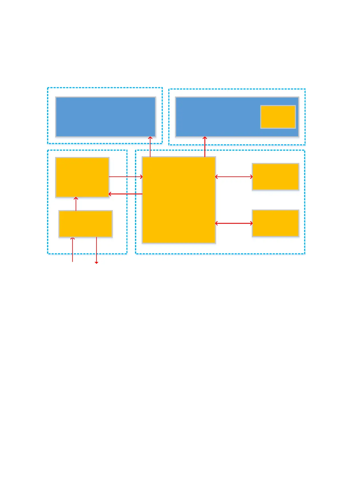
The power supply function is shown as below. The power supply unit can be divided into AC unit
and DC unit from the aspect of power supply transfer flow.
Figure 4-12 Schematic diagram of power supply unit
DC unit includes DC-DC board, PHV board, battery assembly and 24V to 12V power conversion
board.
AC unit includes AC-DC module and AC connecting board.
Closely related to ultrasound services, the voltage circuits in DC part are quite large, in which the
performance also occupies high-performance. The coupling of DC part keeps tight as well. At the
same time, the space arrangement also keeps close to ultrasound service. However, AC, to some
extent, couples little with ultrasound service. The volume is comparatively larger, which may lead
away from ultrasound service.
The battery assembly, 24V to 12V power conversion board and AC unit are located below the base.
 Loading...


