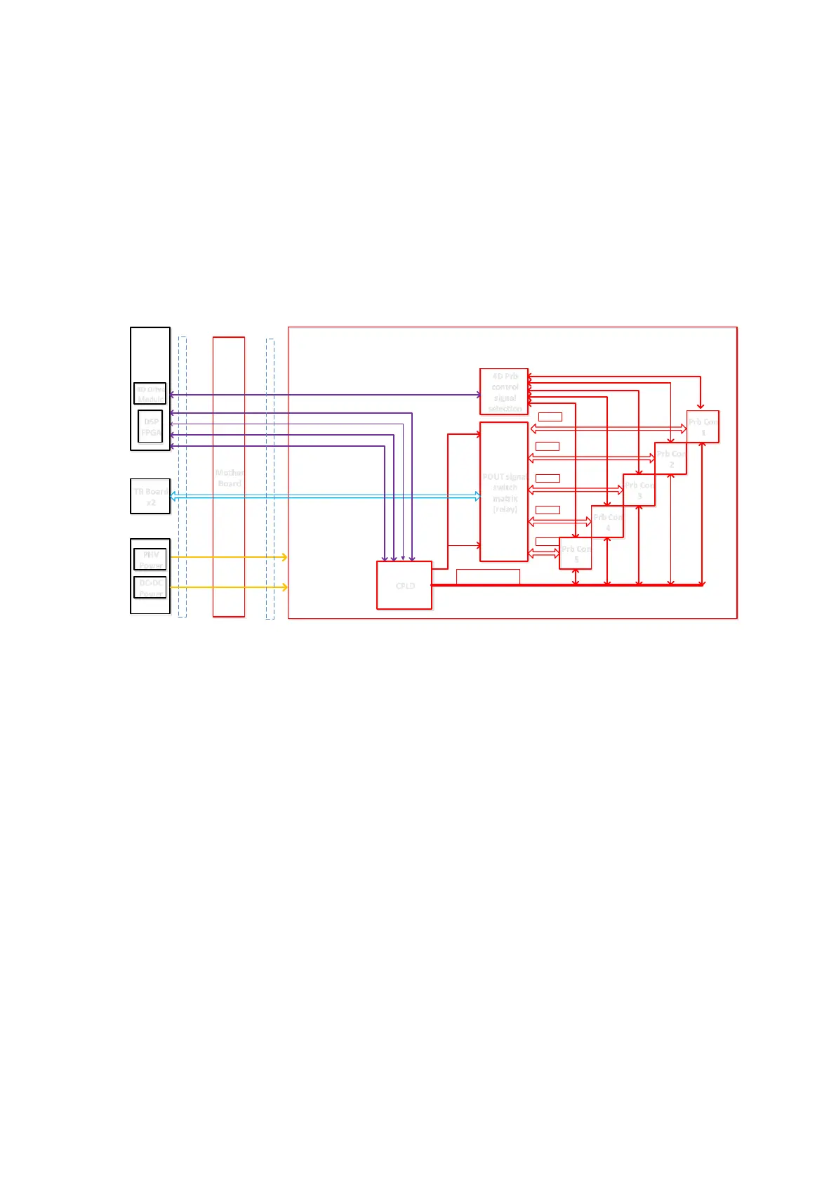
Fig 4-3 Schematic diagram of the probe board
The probe board offers the connection to the probe, and connects the channel of probe's port to the
channel of receiving/transmitting module in main unit. The probe board is subordinate to the engine
board, and manages the probe with the engine board. The functions of probe management:
◼ The notice for probe’s change when it is in the place.
Each in-place signal of the probe is connected to CPLD. CPLD informs DSP_FPGA via an
interruption as each time the change occurs.
◼ General control of the probe - power supply management
CPLD manages the power-up and power-down of each probe’s socket.
Supply the power to flash when accessing to ID as the probe is connected. Enable the probe in
which the channel needs to be switched. The switch circuit inside the probe also needs the
power supply.
After the probe is unplugged, shut down the power supply to the probe and notify the engine
board of stopping transmitting.
◼ General control of the probe -probe recognition
CPLD obtains ID code as SPI accesses to each Flash inside the probe and informs
DSP_FPGA via SPI.
◼ The interconnection to socket's signal
The receiving and transmitting POUT signal of regular probe can be switched among many
probes on the realization of CPLD controlling the relay.
 Loading...


