EasyManuals Logo
Home>Mindray>Diagnostic Equipment>DC-80A

Mindray DC-80A Service Manual

Mindray DC-80A
305 pages
To Next Page IconTo Next Page
To Previous Page IconTo Previous Page
Page #55 background imageLoading...
Page #55 background image
Product Principle 4-1
4 Product Principle
4.1 Hardware System Diagram
PHV Board
TR
FPGA
CW
Board
DSP
FPGA
4D&TEE
Board
Pen Probe Conn
Engine Brd
TR_A Board
Clock
TR
FPGA
TR_B Board
TR
FPGA
TR_C Board
DataDataData
DDR
ATGC
Probe Various Signals
CPLD
Probe
Signal
Switch
Prb Con A
POUT(64)
Present/ID
Probe Board
Power
POUT(64) POUT(64)
Probe Management
PHV Control
Battery*2
24V to 12V Power
Conversion Board
AC-DC Module
AC Connecting
Board
AC Input
TX/RX
TX/RX
TX
RX
TX
RX
TX
RX
Front End
Back End
Power
PHV
Sampling
Scan Status
PHV
Sync
AC output
Control
PHV Control
Monitoring
PCI
-E Bus
Reset
Config
.
Status
JTAG
Touch Screen Device
Hard Disk/DVD-RW
Speaker
Control Panel
Primary Display Device
Secondary Display Device Wireless Network
Digital Video Output
Audio Output
Printer
Analog Video Output
USB Ports
Wired Network
Fans
PC Module GPU Module
MF FPGA
Back End Monitoring
IO Expansion
DVR Module
PC Unit
PC Manager
Microphone
Medical Positioning
Module
Communication
Physiological Signal
Module
IO Interfaces and Devices
Communication
Reset/Control/Clocks
Auxiliary
Output
for Printer
and User
Prb Con B
Prb Con C
Prb Con D
Prb Con E
24V output
12
V output
128G mSATA
SSD
1T
SATA HDD
Bottom Power Box
DC-DC Board
DC-DC
Power
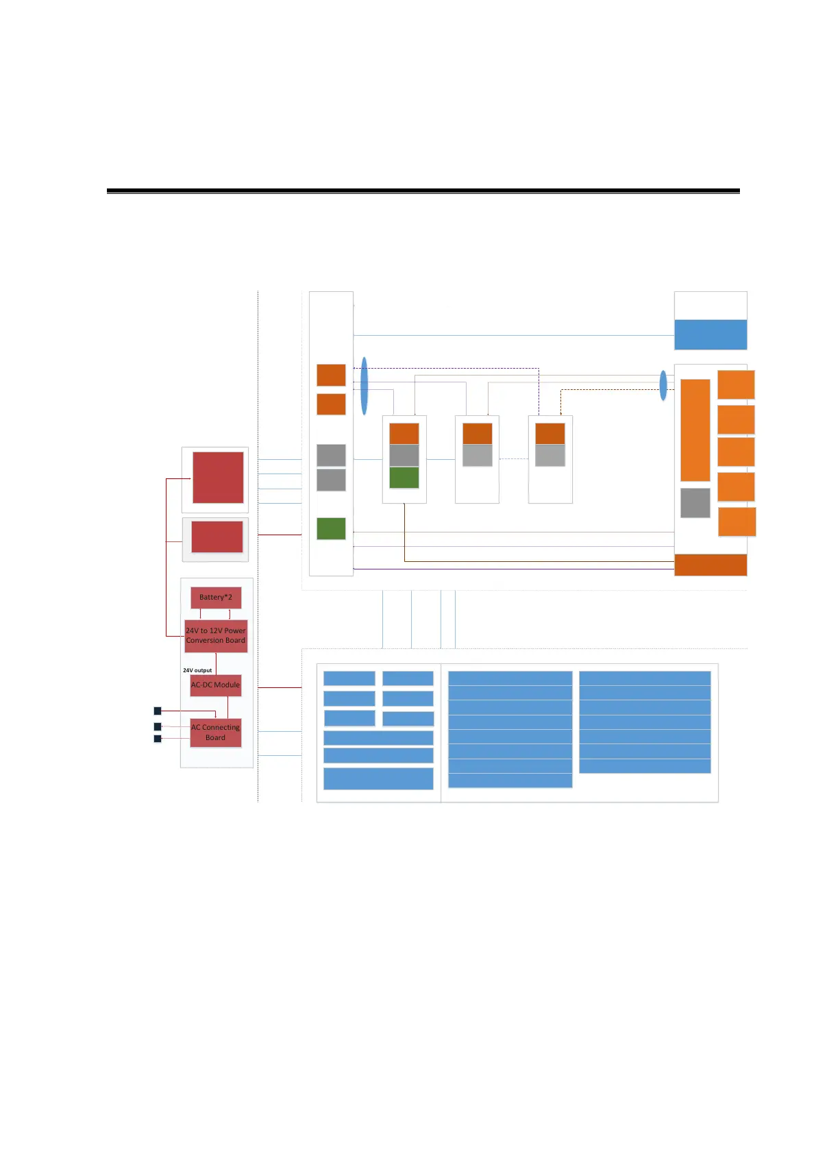
Figure 4-1 of Hardware system diagram
Note: The TR C board is reserved, and not configured. The dotted lines are signal cables
connecting to TR C board, which are also not configured.
The ultrasound device can be divided into three units according to its functions:
â—¼ Front-end unit: is in charge of the scan function of the ultrasound imaging system, and sends
the pre-processed imaging data to the back-end unit for post-process. The engine board takes
charge of front-end unit. The elements are shown above:
âš« The uploaded data on TR64 boards (TR_A and TR_B) are wired in daisy chain and sent to
the engine board.
âš« Control interface, the clock, Rate, sub-module information management (in the place,
board ID) are all based on the engine board, which distributes to other sub-modules.

Table of Contents

Other manuals for Mindray DC-80A

Questions and Answers:

Question and Answer IconNeed help?

Do you have a question about the Mindray DC-80A and is the answer not in the manual?

Mindray DC-80A Specifications

General IconGeneral
BrandMindray
ModelDC-80A
CategoryDiagnostic Equipment
LanguageEnglish

Related product manuals