11-8 System Diagnosis and Support
11.3 Alarming and Errors
The system is equipped with alarming function. When the machine fails, it pops up the alarming
dialogue box, and simultaneously generates LOG file which is saved in the system log. The LOG
file is saved under D:\DC80A\LOG.
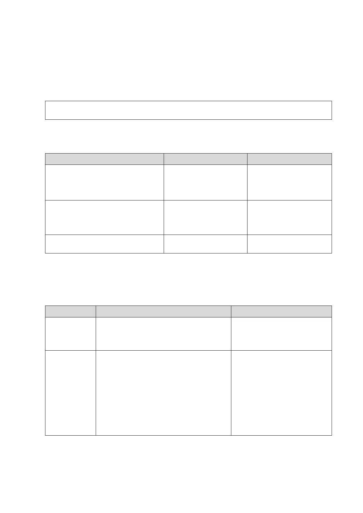
11.3.1 Battery Error
Note: “% s” in the system information is defined according to the battery’s position (in the left/right of
the electronic assembly); “%f” means the value of the over-temperature.
11.3.2 Abnormal Voltage of System Power
The asterisk “***” represents the time in LOG record. The format is: 2011-6-12
14:15:15
Battery communication is abnormal.
The capacity of the battery cannot
appear properly. The current battery is
unusable.
Check the battery
connection or replace the
battery.
Battery over-temperature, Please
connect AC power supply, or Power-off.
%s Battery temperature is
out of range temp,Battery
temperature is: %f
centigrate
Connect AC power, or
power off the system and
wait until the temperature is
normal.
Battery error. Discharge/charge does
work.
The real-time
battery runs
out, please
replace it.
*** System Monitor: Power supply alert!
[XXX], Current voltage: [VVV] V, Limit
voltage:[LLL]~[HHH]V
*** System Monitor: Power supply alert!
[XXX], Current voltage: [VVV] V, Limit
voltage:[LLL]~[HHH]V
[XXX] represents voltage name, [VVV]
represents the current value, and [LLL]-[HHH]
represents the upper and lower limits. The
voltage names respectively are:
Back-end power supply: VDD18, VDD25,
VDD12, VCC, D5V, 12V_ACDC, D3V3
Front-end power supply: A5V7,A6V,A2V1
1. If a certain segment of the
circuit among D5V, 12V_ACDC,
D3V3, A5V7, A6V and A2V1
goes higher or lower, replace
DC-DC board.
2 If a certain segment of the
circuit among VDD18, VDD25,
VDD12 and VCC goes higher or
lower, replace the PC carrier
board.
 Loading...


