_i
Chapter 12 Chassis electrical system
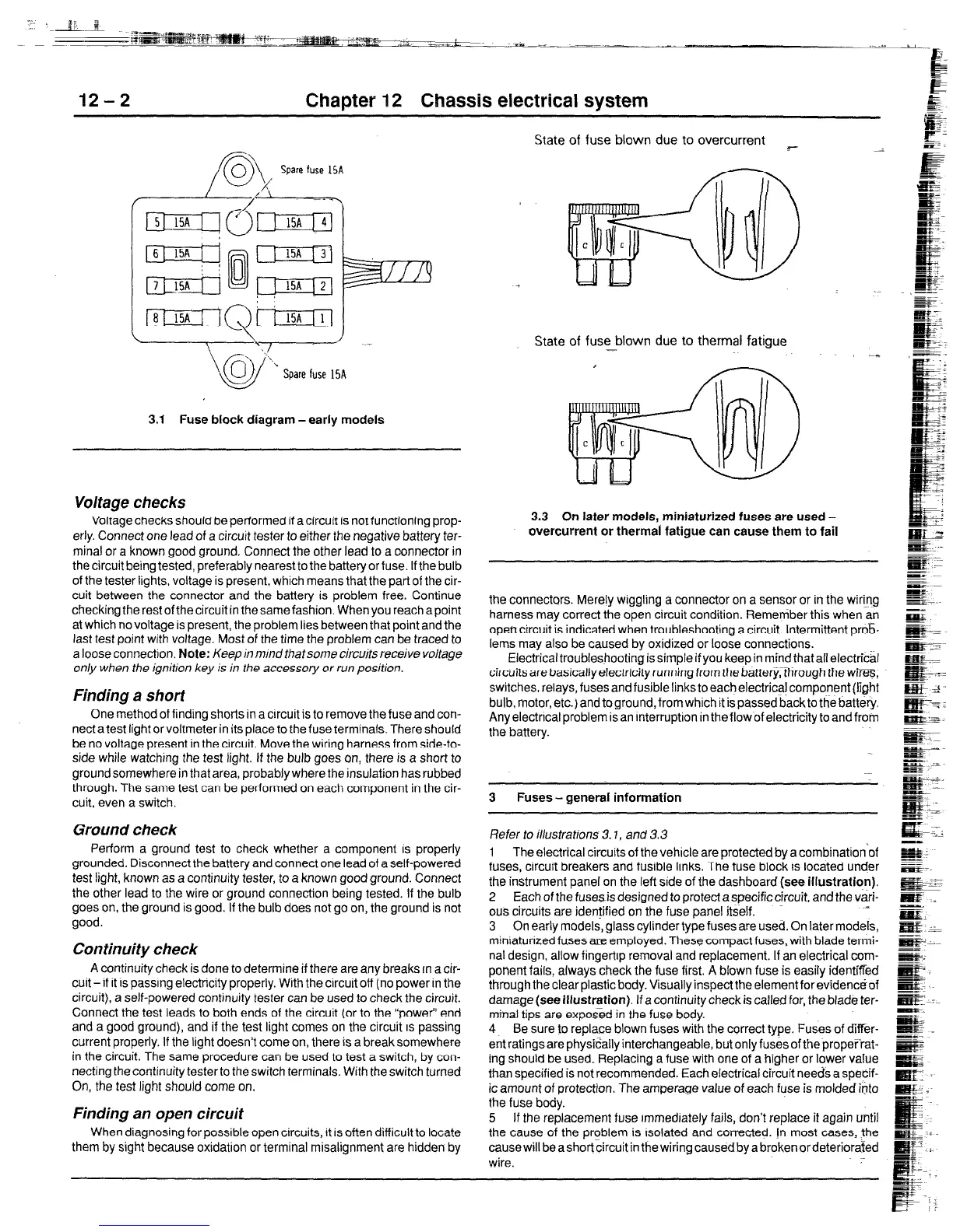
Spare fuse 15A
3.1 Fuse block diagram -early models
Voltage checks
Voltage checks should be performed if acircuit is not functioning prop-
erly. Connect one lead of a circuit tester to either the negative battery ter-
minal or a known good ground. Connect the other lead to a oonnector in
the circuit being tested, preferably nearest to the battery or fuse. If the bulb
of the tester lights. voltage is present, which means that the part of the cir-
cuit between the connector and the battery is problem free. Continue
checking therestofthecircuit in thesamefashion. When you reach apoint
at which no voltage is present, the problem lies between that point and the
last test point with voltage. Most of the time the problem can be traced to
a loose connection. Note: Keep in m/ndthatsome circuits receive voltage
only when the ignition key is in the accessory or run position.
Finding a short
One method of finding shorts in a circuit is to remove the fuse and con-
nect a test light or voltmeter in its place to the fuse terminals. There should
be no voltage present in the circuit. Move the wiring harness from side-to-
side while watching the test light. If the bulb goes on, there is a short to
ground somewhere in that area, probably where the insulation has rubbed
through. The same test can be performed on each component in the cir-
cuit, even a switch.
Ground check
Perform a ground test to check whether a component is properly
grounded. Disconnect the battery and connect one lead of a self-powered
test light, known as a continuity tester, to a known good ground. Connect
the other lead to the wire or ground connection being tested. If the bulb
goes on, the ground is good. If the bulb does not go on, the ground is not
good.
Continuity check
A continuity check is done to determine if there are any breaks rn a cir-
cuit - if it is passing electricity properly. With the circuit off (no power in the
circuit), a self-powered continuity tester can be used to check the circuit.
Connect the test leads to both ends of the circuit (or to the “power” end
and a good ground), and if the test light comes on the circuit IS passing
current properly. If the light doesn’t come on, there is a breaksomewhere
in the circuit. The same procedure can be used to test a switch, by con-
necting the continuity tester to the switch terminals. With the switch turned
On, the test light should come on.
Finding an open circuit
When diagnosing for possible open circuits, it is often difficult to locate
them by sight because oxidation or terminal misalignment are hidden by
State of fuse
blown
due to overcurrent ~-
State of fuse blown due to thermal fatigue
-*
3.3 On later models, miniaturized fuses
are
used -
overcurrent or thermal fatigue can cause them to fail
the connectors. Merely wiggling a connector on a sensor or in the wiring
harness may correct the open circuit condition.
Remember
this when an
open circuit is indicated when troubleshooting a circuit. Intermittent pro&
lems may also be caused by oxidized or loose connections.
Electrical troubleshooting is simple if you keep in mind that all electrical
circuits are basically electricity running from the batteryythrough the wZ%,
switches. relays, fuses and fusible links to each electrica! component (fight
bulb, motor, etc.) and to ground, from which it is passed backto the battery.
Any electrical problem is an interruption in the flow of electricity to and from
the battery.
3 Fuses - general information
Refer to illustrations 3.7, and 3.3
1 The electrical circuits of the vehicle are protected by a combination of
fuses, circuit breakers and fusible links. The fuse block is
located under
the instrument panel on the left side of the dashboard (see illustration).
2 Each of the fuse@ designed to protect a specific circuit, and the vari-
ous circuits are identified on the fuse panel itself.
3 On early models, glass cylinder type fuses are used. On later
models,
miniaturized fuses are employed. These compact fuses, with blade termi-
nal design, allow fingertrp removal and replacement. If an electrical com-
ponent fails, always check the fuse first. A blown fuse is easily identified
through the clear plastic body. Visually inspect the element for
evidenciof
damage
(see illustration). If a continuity check is called for, the blade ter-
minal tips are exposed in the fuse body.
4 Be sure to replace blown fuses with the correct type. Fuses of
difkr-
ent ratings are physically interchangeable, but only fuses of the propet%%-
ing should be used. Replacing a fuse with one of a higher or lower value
than specified is not recommended. Each electrical circuit needs a specif-
ic amount of protection. The amperage
value of each
fuse
is molded into
the fuse body.
5 If the replacement fuse rmmedrately fails, don’t replace it again until
the cause of the problem is rsolated and corrected. In most cases, the
causewill beashortcircuit in thewiring
causedbya
brokenordeteriorated
wire.
 Loading...