2C-14
Chapter 2 Part C 3.OL V6 engine
16.3 Measuring cam lobe height with a micrometer
17.15 Oil pan bolt tightening sequence
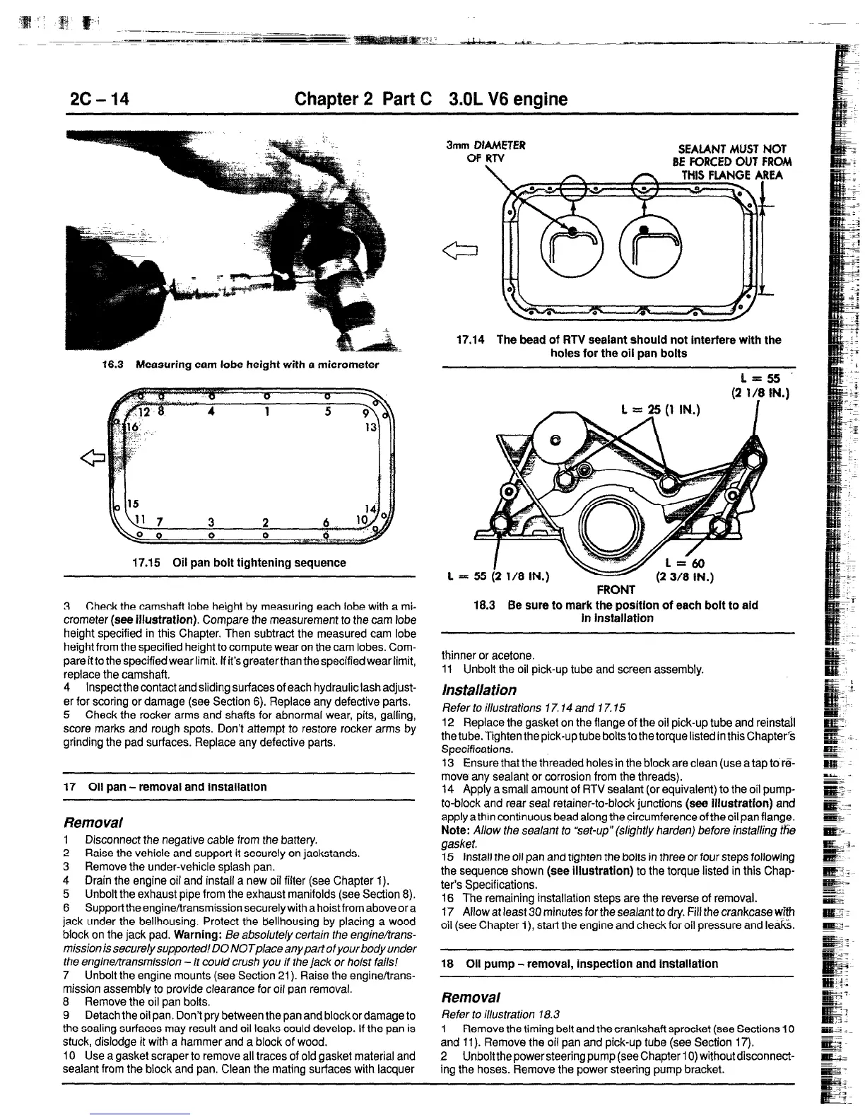
3 Check the camshaft lobe height by measuring each lobe with a mi-
crometer
(see illustration).
Compare the measurement to the cam lobe
height specified in this Chapter. Then subtract the measured cam lobe
height from the specified height to compute wear on the cam lobes. Com-
pare it to the specifiedwear limit. If it’s greaterthan the specifiedwear limit,
replace the camshaft.
4
Inspect the contact and sliding surfaces of each hydraulic lash adjust-
er for scoring or damage (see Section 6). Replace any defective parts.
5 Check the rocker arms and shafts for abnormal wear, pits, galling,
score marks and rough spots. Don’t attempf to restore rocker arms by
grinding the pad surfaces. Replace any defective parts.
17 Oil pan - removal and installation
Removal
1 Disconnect the negative cable from the battery.
2 Raise the vehicle and support it securely on jackstands.
3 Remove the under-vehicle splash pan.
4
Drain the engine oil and install a new oil filter (see Chapter 1).
5 Unbolt the exhaust pipe from the exhaust manifolds (see Section 8).
6 SupporttheengineAransmission securely with a hoist from above or a
jack under the bellhousing. Protect the bellhousing by placing a wood
block on the jack pad.
Warning:
Be absolutely cerfain the engine/trans-
missionis securely supported! DO NOTplace anypartofyourbodyunder
the engine/transmission - it could crush you if the jack or hoist fails!
7 Unbolt the engine mounts (see Section 21). Raise the engineffrans-
mission assembly to provide clearance for oil pan removal.
8 Remove the oil pan bolts.
9
Detach the oil pan. Don’t pry between the pan and block or damage to
the sealing surfaces may result and oil leaks could develop. If the pan is
stuck, dislodge it with a hammer and a block of wood,
10 Use a gasket scraper to remove all traces of old gasket material and
sealant from the block and pan. Clean the mating surfaces with lacquer
3mm DIAMETER
OFRTV
SEALANT
MUST NOT
BE FORCED OUT FROM
17.14 The bead of RTV sealant should not interfere with the
holes for the oil pan bolts
FRONT ’
18.3 Be sure to mark the positlon of each bolt to aid
In Installation
thinner or acetone.
11 Unbolt the oil pick-up tube and screen assembly.
Installation
Refer to illustrations 17.14 and 17.15
12 Replace the gasket on the flange of the oil pick-up tube and reinstall
the tube. Tighten the pick-up tube bolts to the torque listed in this Chapter’%
Specifications.
13 Ensure that the threaded holes in the block are clean (use atap to re-
move any sealant or corrosion from the threads).
14 Apply a small amount of RTV sealant (or equivalent) to the oil pump-
to-block and rear seat retainer-to-block junctions
(see illustration)
and
apply a thin continuous bead along the circumference of the oil pan flange.
Note:
Allow the sealant to “set-up” (slightly harden) before installing #Ye
gasket.
15 Install the oil pan and tighten the bolts in three or four steps following
the sequence shown
(see illustration)
to the torque listed in this Chap-
ter’s Specifications.
16 The remaining installation steps are the reverse of removal.
17 Allow at least 30 minutes for the sealant to dry. Fill the crankcase with
oil (see Chapter i), start the engine and check for oil pressure and leaf&
18 Oil pump - removal, inspection and instalfatlon
Removal
Refer to illustration 18.3
1
Remove the timing belt and the crankshaft sprocket (see Sections 10
and 11). Remove the oil pan and pick-up tube (see Section 17).
2 Unboltthepowersteering pump (seechapter 10) withoutdisconnect-
ing the hoses. Remove the power steering pump bracket.
 Loading...