4-30
Chapter 4 Fuel and exhaust systems
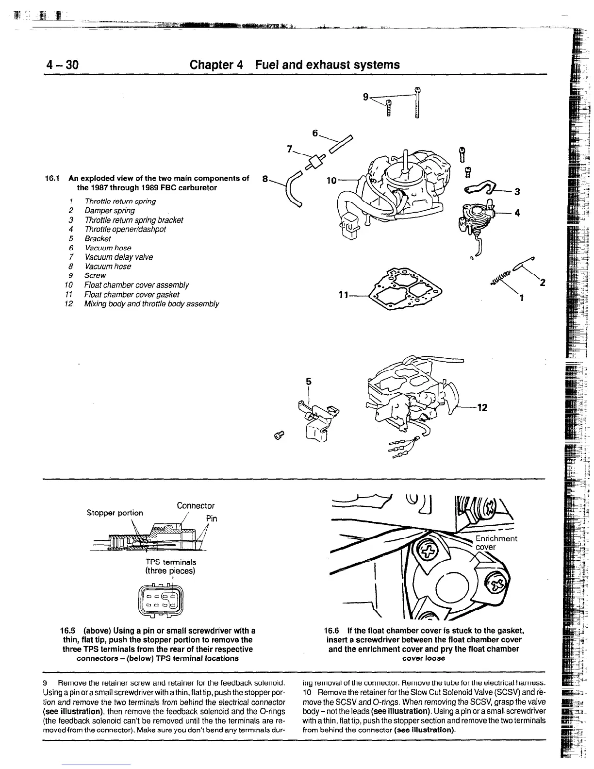
f 6.1 An exploded view of the two main components of
the f 987 through f 989 FBC carburetor
1
Throttle return spring
2 Damper spring
3 Throttle return spting bracket
4 Throttle opener/dashpot
5 Bracket
6 Vacuum hose
7 Vacuum delay valve
8 Vacuum hose
9 Screw
IO Float chamber cover assembly
11 Float chamber cover gasket
12 Mixing body and throttle body assembly
8
,12
Stopper portion
Connector
/ Pin
TPS terminals
(three pieces)
f 6.5 (above) Using a pin or small screwdriver with a
thin, fiat tip, push the stopper portion to remove the
three TPS terminals from the rear of their respective
connectors - (below) TPS terminal locations
f 6.6 if the float chamber cover is stuck to the gasket,
insert a screwdriver between the float chamber cover
and the enrichment cover and pry the float chamber
cover loose
9 Remove the retainer screw and retainer for the feedback solenoid,
Using a pin or a small screwdriver with a thin, flat tip, push the stopper por-
tion and remove the two terminals from behind the electrical connector
(see illustration),
then remove the feedback solenoid and the O-rings
(the feedback solenoid can’t be removed until the the terminals are re-
moved from the connector). Make sure you don’t bend any terminals dur-
ing removal of the connector. Remove the tube for the electrical harness.
10 Remove the retainer for the Slow Cut Solenoid Valve (SCSV)
and rii-
move the SCSV and O-rings. When removing the SCSV, grasp the valve
body- not the leads
(see illustration).
Using a pin or a small screwdriver
with a thin, flat tip, push the stopper section and remove the two terminals
from behind the connector
(sea illustration).
 Loading...