Chapter 2 Part C 3.OL V6 engine
11&b . . . to push the seal into the bore-the pipe must bear
against the outer edge of the seal as the bolt is tightened
.
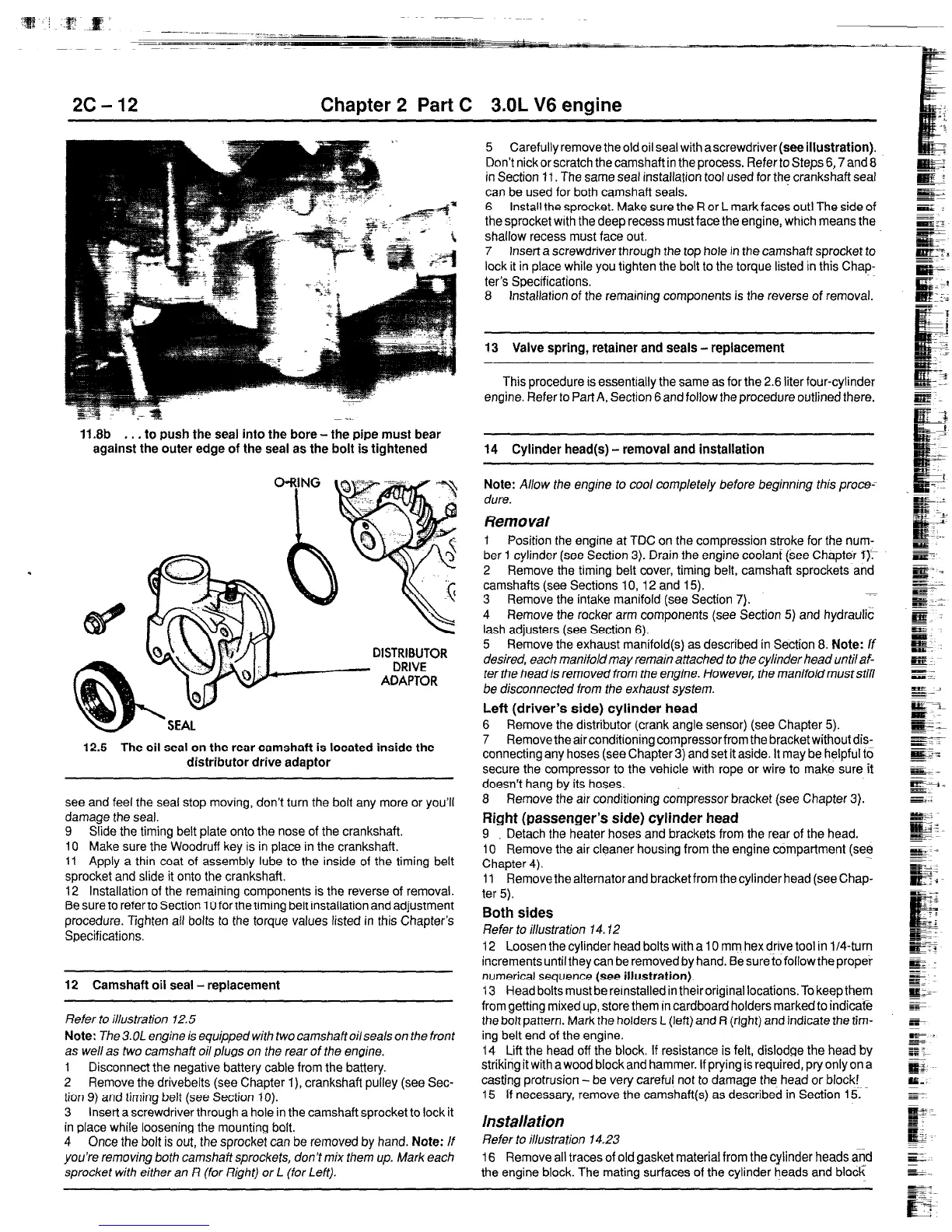
12.5 The oil seal on the rear camshaft is located inside the
distributor drive adaptor
see and feel the seal stop moving, don’t turn the bolt any more or you’ll
damage the seal.
9 Slide the timing belt plate onto the nose of the crankshaft.
10 Make sure the Woodruff key is in place in the crankshaft.
11 Apply a thin coat of assembly lube to the inside of the timing belt
sprocket and slide it onto the crankshaft.
12 Installation of the remaining components is the reverse of removal.
Be sure to refer to Section 10 for the timing belt installation and adjustment
procedure. Tighten all bolts to the torque values listed in this Chapter’s
Specifications.
12 Camshaft oil seal - replacement
Refer to illustration 72.5
Note:
The 3.OL engine is equipped with two camshaft oilseals on the front
as well as two camshaft oil plugs on the rear of the engine.
1 Disconnect the negative battery cable from the battery.
2 Remove the drivebelts (see Chapter l), crankshaft pulley (see Sec-
tion 9) and timing belt (see Section IO).
3 Insert a screwdriver through a hole in the camshaft sprocket to lock it
in place whiie loosening the mounting bolt.
4 Once the bolt is out, the sprocket can be removed by hand. Note: /f
you’re removing both camshaft sprockets, don’t mix them up. Mark each
sprocket with either an R (for Right) or L (for Left).
5 Carefully remove the old oil seal with
a
screwdriver
(see illustration).
Don’t nick or scratch the camshaft in the process. Refer to Steps 6,7 and 8
in Section 11. The same seal installation tool used for the crankshaft seal
can be used for both camshaft seals.
6 Install the sprocket. Make sure the R or L mark faces out! The side of
the sprocket with the deep recess must face the engine, which means the
shallow recess must face out.
7 Insert a screwdriver through the top hole in the camshaft sprocket to
lock it in place while you tighten the bolt to the torque listed in this Chap-
ter’s Specifications.
8 Installation of the remaining components is the reverse of removal.
13 Valve spring, retainer and seals - replacement
This procedure is essentially the same as for the 2.6 liter four-cylinder
engine. Refer to Part A, Section 6 and follow the procedure outlined there.
14 Cylinder head(s) - removal and installation
Note:
Allow the engine to cool completely before beginning this proce=
due.
Removal
1 Position the engine at TDC on the compression stroke for the num-
ber 1 cylinder (see Section 3). Drain the engine coolanf {see Chapter Q:-
2 Remove the timing belt cover, timing belt, camshaft sprockets and
camshafts (see Sections lo,12 and 15).
3 Remove the intake manifold (see Section 7).
4 Remove the rocker arm components (see Section 5) and hydraulic
lash adjusters (see Section 6).
5 Remove the exhaust manifold(s) as described in Section 8. Note: If
desired, each manifold may remain attached to the cylinder head until af-
ter the head is removed from the engine. However, the manifold must still
be disconnected from the exhaust system.
Left (driver’s side) cylinder head
6 Remove the distributor (crank angle sensor) (see Chapter 5).
7 Remove the air conditioning compressor from the bracket without dis-
connecting any hoses (see Chapter 3) and set it aside. It may be helpful to
secure the compressor to the vehicle with rope or wire to make sure it
doesn’t hang by its hoses.
8 Remove the air conditioning compressor bracket (see Chapter 3).
Right (passenger’s side) cylinder head
9 Detach the heater hoses and brackets from the rear of the head.
IO Remove the air cleaner housing from the engine compartment (see
Chapter 4).
11 Remove the alternator and bracket from the cylinder head (see Chap-
ter 5).
Both sides
Refer to illustration 14.12
12 Loosen the cylinder head bolts with a 10 mm hex drive tool in l/Cturn
increments until they can be removed by hand. Be sure to follow the proper
numerical sequence (see
illustration).
13 Head bolts must be reinstalled in their original locations. To keep them
from getting mixed up, store them in cardboard holders marked to indicatG
the bolt pattern. Mark the holders L (left) and R (right) and indicate the tim-
ing belt end of the engine.
14 Lift the head off the block. If resistance is felt, dislodge the head by
striking it with a wood block and hammer. If prying is required, pry only on a
casting protrusion - be very careful not to damage the head or block!
15 If necessary, remove the camshaft(s) as described in Section 15.
Installation
Refer to illustration 14.23
16 Remove all traces of old gasket material from the cylinder heads a$
the engine block. The mating surfaces of the cylinder heads and block
 Loading...