Chapter 2 Part C 3.OL V6 engine 2C-15
8
6’ ‘7
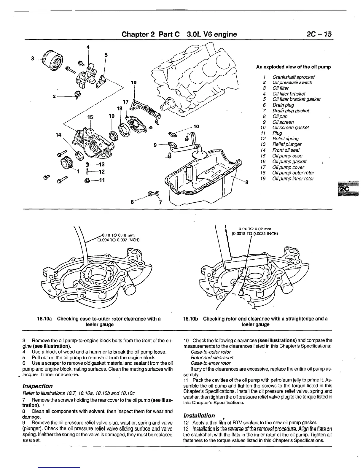
An exploded view of the oil pump
1
Crankshaft sprocket
2 Oil pressure switch
3 Oil filter
4 Oil filter bracket
5 Oil filter bracket gasket
.6
Drain plug
7 Draiii plug gasket
8 Oil pan
9 Oil screen
10 Oil screen gasket
11
Plug
12
Relief spring
13
Relief
plunger
14 Front oil seal
15
Oil pump case
16
Oil
pump gasket ,
17 Oil pump cover
18 Oil pump outer rotor
19 Oil pump inner rotor
0.10 TO 0.18 mm
\\
0.04 TO 0.09 mm
(0.0015 TO 9.0035 INCH)
I
18.10a Checking case-to-outer rotor clearance with a
feeler gauge
3 Remove the oil pump-to-engine block bolts from the front of the en-
gine (see
illustration).
4 Use a block of wood and a hammer to break the oil pump loose.
5 Pull out on the oil pump to remove it from the engine block.
6 Use a scraper to remove old gasket material and sealant from the oil
pump and engine block mating surfaces. Clean the mating surfaces with
t lacquer thinner or acetone.
Inspection
Refer to illustrations 18.7, 18. IOa, 18. lob and 18.10~
7 Remove the screws holding the rear cover to the oil pump
(see iiius-
tration). i
8 Clean all components with solvent, then inspect them for wear and
damage.
9 Remove the oil pressure relief valve plug, washer, spring and valve
(plunger). Check the oil pressure relief valve sliding surface and valve
spring. If either the spring or the valve is damaged, they must be replaced
as a set.
18.10b Checking rotor end clearance with a straightedge and a
feeler gauge
10 Check the following clearances (see
illustrations)
and compare the
measurements to the clearances listed in this Chapter’s Specifications:
Case-to-outer rotor
Rotor end clearance
Case-to-inner rotor
If any of the clearances are excessive, replace the entire oil pump as-
sembly.
11 Pack the cavities of the oil pump with petroleum jelly to prime it. As-
semble the oil pump and tighten the screws to,the torque listed in this
Chapter’s Specifications. Install the oil pressure relief valve, spring and
washer, then tighten the oil pressure relief valve plug to the torque listed in
this Chapter’s Specifications.
Ins talla tion
12 Apply a thin fillfl of RTV sealant to the new oil pump gasket.
13 Installation is the reverse of the removal procedure. Align the flats on
the crankshaft with the flats in the inner rotor of the oil pump. Tighten all
fasteners to the torque values listed in this Chapter’s Specifications.
 Loading...