12-8 Chapter 12 Chassis electrical system
15.1 Removing the plastic cover screws
(1966 and earlier models)
15.4 Lifting off the printed circuit board
(1966 and earlier models)
15 instrument cluster-disassembly and reassembly
-
Refer to illustrafions 15.1, 15.4 and 15.8
1986 and earlier models
1 Remove the screws holding the clear plastic cover and trim ring in
place and lift them off (see illustration).
2 Turn the cluster over and remove the nuts from the studs on the right
side. Unscrew the buzzer mounting screw and remove the buzzer.
3 Remove the bulb holders from the printed circuit board by turning
them counterclockwise.
4 Remove the self-tapping screws and the machine screws. The ma-
chine screws have two different size threads, so be sure they are returned
to the exact same locations they were removed from. Carefully lift the
printed circuit board off the instrument cluster (see illustration).
5 The speedometer is held in position with two screws.
6 Reassembly is the reverse of disassembly.
1987 and later models
7 Remove the two lower screws holding the clear plastic cover.
8 Turn the cluster over and remove the self-tapping screws (see illus-
tration).
9 Remove the bulb holders from the printed circuit board by turning
them counterclockwise.
10 Reassembly is the reverse of disassembly.
a
D
W”
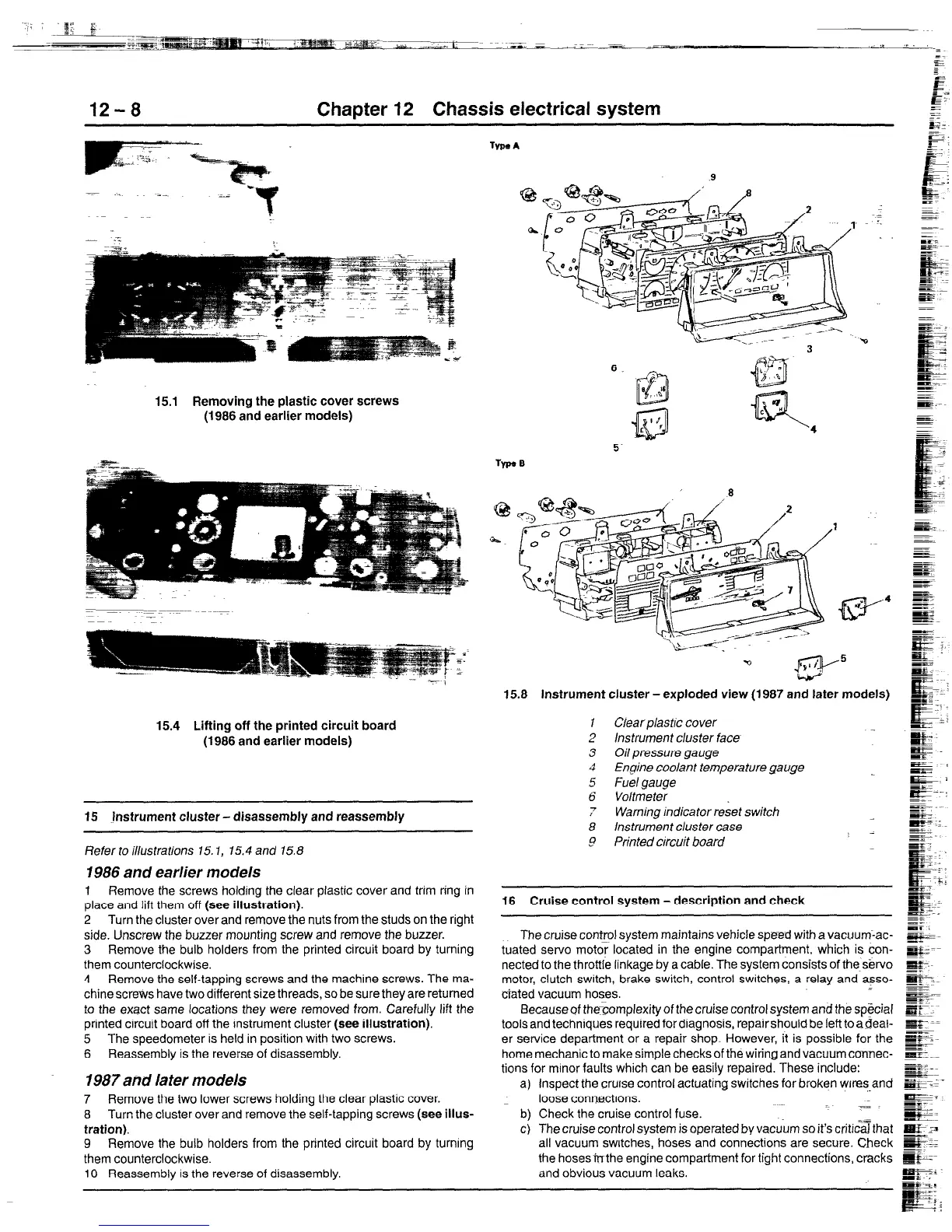
15.8 Instrument cluster-exploded view (1987 and later models)
ClearplastIc cover
Instrument cluster face
Oil pressure gauge
Engine coolant temperature gauge
Fuel gauge
Voltmeter
Warning indicator reset switch
instrument cluster case
Printed circuit board
16 Cruise control system - description and check
The cruise control system maintains vehicle speed with a vacuum:ac-
tuated servo motor located in the engine compartment. which is con-
nected to the throttle linkage by a cable. The system consists of the s&vo
motor, clutch switch, brake switch, control switches, a relay and asso-
ciated vacuum hoses.
Because of the’complexity of the cruise control system and the sp&ial
toolsand techniques required for diagnosis, repairshould be ieft to aBeal-
er service department or a repair shop. However, it is possible for the
home mechanic to make simple checks of the wiring and vacuum connec-
tions for minor faults which can be easily repaired. These include:
a) Inspect the cruise control actuating switches for broken wires-and
loose conwctlons.
b) Check the cruise control fuse.
c) The cruise control system is operated by vacuum so it’s criti;Gthat
all vacuum switches, hoses and connections are secure. Check
the hosesfrrthe engine compartment for tight connections, cracks
and obvious vacuum leaks.
 Loading...