Chapter 2 Part C 3.OL V6 engine
2C-5
surfaces with lacquer thinner or acetone. If there’s sealant or oil on the -
mating surfaces when the cover is installed, oil leaks may develop.
15 If necessary, clean the mounting screw threads with a die to remove
any corrosion and restore damaged threads. Make sure the threaded
holes in the head are clean -run a tap into them to remove corrosion and
restore damaged threads.
16 The gaskets should be mated to the covers before the covers are in-
stalled. Apply a bead of RTV sealant to the cover in the areas indicated
(see illustration),
then position the gasket inside the cover and allow the
sealant to set up so the gasket adheres to the cover. If the sealant isn’t
allowed to set, the gasket may fall out of the cover as it’s installed on the
engine. *
17 Carefully position the cover on the head and install the bolts.
18 Tighten the boltsin three or four steps to the torque listed in this Chap-
ter’s Specifications.
19 The remaining installation steps are the reverse of removal.
20 Start the engine and check carefully for oil leaks as the engine warms
up.
Sealing
coating
A
agent
location
4.16 it’s not necessary to use RIV gasket sealer on the inside of
the gasket if the gasket is a tight fit and does not budge once it is
installed inside the valve cover - it is necessary to apply RTV to
the edges (arrows) on the outside of the gasket where it mates
with the camshaft seals
OIL INTAKE WAR
HAS EXI-RA HOLE
IN BOTrOM
43 2 1
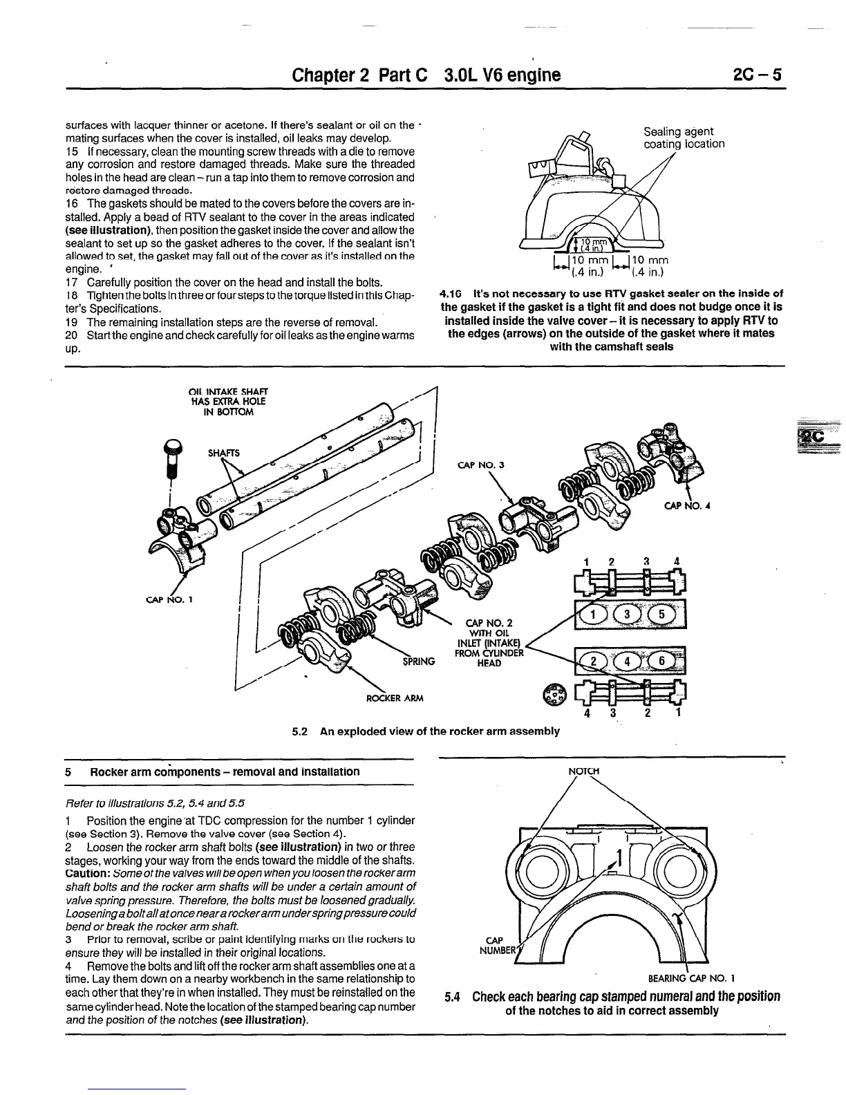
5.2 An exploded view of the rocker arm assembly
5 Rocker arm components-removal and installation
NOTCH
/\
Refer to illustrations 5.2, 5.4 and 5.5 / \
1 Position the engine‘at TDC compression for the number 1 cylinder
(see Section 3). Remove the valve cover (see Section 4).
2 Loosen the rocker arm shaft bolts
(see illustration)
in two or three
stages, working your way from the ends toward the middle of the shafts.
Caution:
Some of fbe valves willbe open when you loosen the rockerarm
shaft bolts and the rocker arm shafts will be under a certain amount of
valve spring pressure. Therefore, the bolts must be loosenedgradually.
Loosening a boltallat once neara rockerarm underspringpressure could
bend or break the rocker arm shaft.
3 Prior to removal, scribe or paint identifying marks on the rockers to
ensure they will be installed in their original locations.
4 Remove the bolts and lift off the rocker arm shaft assemblies one at a
time. Lay them down on
a
nearby workbench in the same relationship to
each otherthat they’re in when installed. They must be reinstalled on the
same cylinder head. Note the location of the stamped bearing cap number
and the position of the notches
(see illustration).
5.4
BEARING-CAP NO. 1
Check each bearing cap stamped numeral and the position
of the notches to aid in correct assembly
 Loading...