2A-16 Chapter 2 Part A 2.6L four-cylinder engine
16.7 Check the driven gear-to-housing
16.8 Check the drive gear-to-housing
16.9 Remove the oil pressure relief
clearance clearance valve spring and measure Its free length
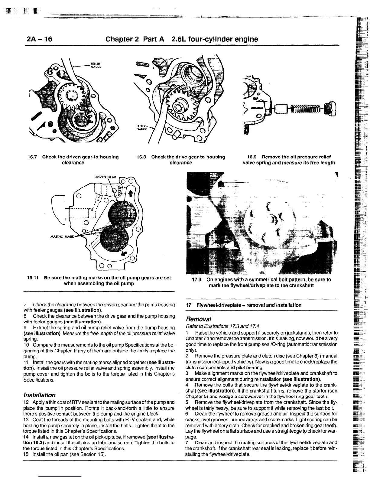
16.11 Be sure the mating marks on the oil pump gears are set
when assembling the oil pump
7 Check the clearance between the driven gear and the pump housing
with feeler gauges
(see illustration).
8 Check the clearance between the drive gear and the pump housing
with feeler gauges
(see illustration).
9 Extract the spring and oil pump relief valve from the pump housing
(see illustration).
Measure the free length of the oil pressure relief valve
spring.
IO Compare the measurements to the oil pump Specifications at the be-
ginning of this Chapter. If any of them are outside the limits, replace the
pump.
11 install thegearswith the mating marks aligned together(see
illustra-
tion).
Install the oil pressure relief valve and spring assembly. Install the
pump cover and tighten the bolts to the torque listed in this Chapter’s
Specifications.
Ins talla tion
12 ApplyathincoatofRTVsealanttothematingsurfaceofthepumpand
place the pump in position. Rotate it back-and-forth a little to ensure
there’s positive contact between the pump and the engine block.
13 Coat the threads of the mounting bolts with RTV sealant and, while
holding the pump securely in place, install the bolts. Tighten them to the
torque listed in this Chapter’s Specifications.
14 Install a new gasket on the oil pick-up tube, if removed
(see illustra-
tion 16.3)
and install the oil pick-up tube and screen. Tighten the bolts to
the torque listed in this Chapter’s Specifications.
15 Install the oil pan (see Section 15).
17.3 On engines with a symmetrical bolt pattern, be sure to
mark the flywheel/driveplate to the crankshaft
17 FlywheeVdriveplate - removal and inslallation
Removal
Refer to illustrations 17.3 and 17.4
1 Raise the vehicle and support it securely on jackstands, then refer to
Chapter 7and remove the transmission. If it’s leaking, now would be a very
good time to replace the front pump seal/O-ring (automatic transmission
only).
2 Remove the pressure plate and clutch disc (see Chapter 8) (manual
transmission equipped vehicles). Now is a good time to check/replace the
clutch components
and
pilot bearing.
3 Make alignment marks on the flywheel/driveplate and crankshaft to
ensure correct alignment during reinstallation
(see illustration).
4 Remove the bolts that secure the flywheel/driveplate to the crank-
shaft
(see illustration).
If the crankshaft turns, remove the starter (see
Chapter 5) and wedge a screwdriver in the flywheel ring gear teeth.
5 Remove the flywheel/driveplate from the crankshaft. Since the fb-
wheel is fairly heavy, be sure to support it while removing the last bolt.
6 Clean the flywheel to remove grease and ofl. Inspect the surface for
cracks, rivet grooves, burned areas and score marks. Light scoring can be
removed with emery cloth. Check for cracked and broken ring gear teeth.
Lay the flywheel on a flat surface and
use a
straightedge to check for war-
paw.
7 Clean and inspect the mating surfaces of the flywheel/driveplate and
the crankshaft. If the crankshaf? rear seal is leaking, replace it before rein-
stalling the fiywheelidriveplate.
 Loading...