Chapter 2 Part C
3.OL V6 engine
-... -. -.. .__.- .-.____ _
ARROW MARK
iCYlINDER HEAD)
\
ARROW hi?(BEARING CAPj
5.5 The arrows on the bearing caps should point in the same
direction as the arrows on the cylinder heads
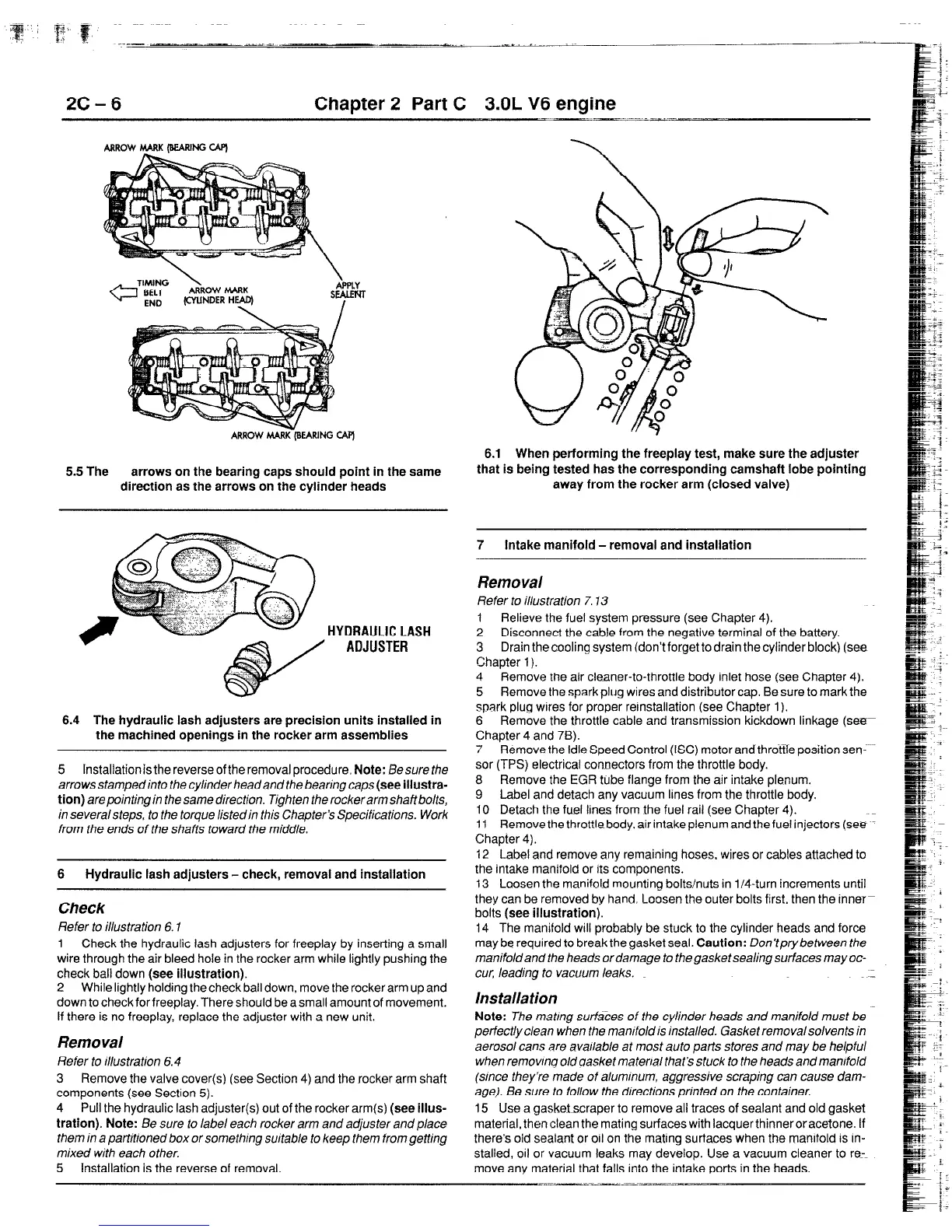
6.1 When performing the freeplay test, make sure the adjuster
that is being tested has the corresponding camshaft lobe pointing
away from the rocker arm (closed valve)
HYDRAULICLASH
ADJUSTER
6.4 The hydraulic lash adjusters are precision units installed in
the machined openings in the rocker arm assemblies
5 Installationis the reverse of the removal procedure. Note: Eesure the
arrows stamped info the cylinder head and the bearing caps (see iiiustra-
tion) arepointing in the same direction. Tighten the rockerarm shaftbolts,
in severalsteps. to the torque listed in this Chapter’s Specifications. Work
from the ends of the shafts toward the middle.
6
Hydraulic lash adjusters-check, removal and installation
Check
Refer to illustration 6.7
1 Check the hydraulic lash adjusters for freeplay by inserting a small
wire through the air bleed hole in the rocker arm while lightly pushing the
check bail down (see illustration).
2 While lightly holding the check ball down, move the rocker arm up and
down to check for freeplay. There should be a small amount of movement.
if there is no freeplay, replace the adjuster with a new unit.
Rem0 val
Refer to illustration 6.4
3 Remove the valve cover(s) (see Section 4) and the rocker arm shaft
components (see Section 5).
4 Pull the hydraulic lash adjuster(s) out of the rocker arm(s) (see iiius-
tration). Note: Be sure to label each rocker arm and adjuster and place
them in a partitioned box or something suitable to keep them from getting
mixed with each other.
5 installation is the reverse of removal.
7
intake manifold-removal and installation
Removal
Refer to illustration 7.13
1
Relieve the fuel system pressure (see Chapter 4).
2 Disconnect the cable from the negative terminal of the battery.
3 Drain the cooling system (don’t forget to drain the cylinder block) (see
Chapter 1).
4 Remove the air cleaner-to-throttle body inlet hose (see Chapter 4).
5 Remove the spark plug wires and distributor cap. Be sure to mark the
spark plug wares for proper rernstallation (see Chapter 1).
6 Remove the throttle cable and transmission kickdown linkage (see
Chapter 4 and 78).
7 Remove the Idle Speed Control (ISC) motor andthrottfe position sen-
sor (TPS) electrical connectors from the throttle body.
8 Remove the EGR tube flange from the air intake plenum.
9 Label and detach any vacuum lines from the throttle body.
10 Detach the fuel lines from the fuel rail (see Chapter 4).
11 Remove the throttle body. air intake plenum and the fuel injectors (see
Chapter 4).
12 Label and remove any remaining hoses. wires or cables attached to
the intake manifold or its components.
13 Loosen the manifold mounting bolts/nuts in l/4-turn increments until
they can be removed by hand. Loosen the outer bolts first. then the inner-
bolts (see illustration).
14 The manifold will probably be stuck to the cylinder heads and force
may be required to break the gasket seal. Caution: Don’tprybetween the
manifoldand the heads ordamage to thegasketsealing surfaces mayoc-
CUT, leading to vacuum leaks.
Installation
Note: The matmg surfaces of the cylinder heads and manifold must be
perfectly clean when the manrfold is installed. Gasket removalsolvents in
aerosol cans are avaIlable at most auto parts stores and may be helpful
when removing old aasket mater/al that’s stuck to the heads and manifold
(since they’re made of alummum, aggressive scraping can cause dam-
age). Be sure to follow the drrections printed on the container.
15 Use a gasket scraper to remove all traces of sealant and old gasket
matertal, then clean the mating surfaces with lacquer thinneroracetone. If
there’s old sealant or oil on the mating surfaces when the manifold is in-
stalled, oil or vacuum leaks may develop. Use a vacuum cleaner to re_=
move any material that falls into the intake ports in the heads.
 Loading...