Chapter 4
Fuel and exhaust systems
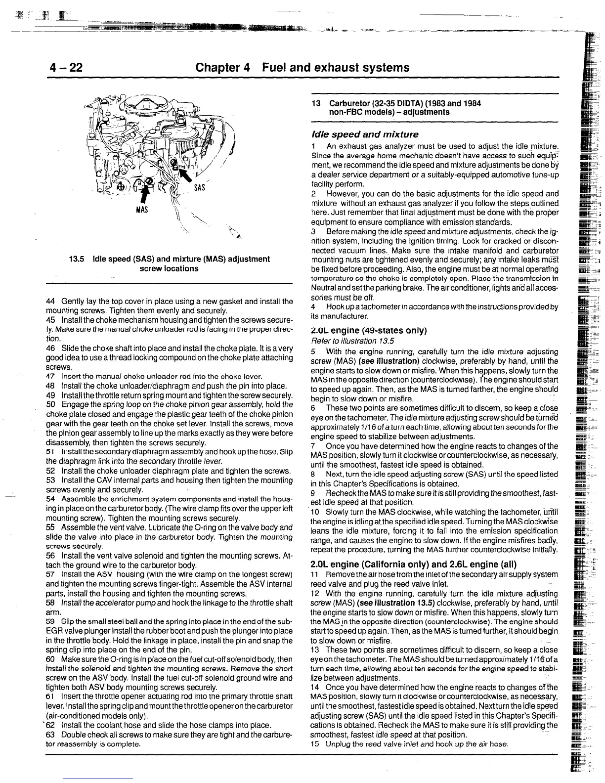
13.5 Idle speed (SAS) and mixture (MAS) adjustment
screw locations
44 Gently lay the top cover in place using a new gasket and install the
mounting screws. Tighten them evenly and securely.
45 Install the choke mechanism housing and tighten the screws secure-
ly. Make sure the manual choke unloader rod is facing in the proper,direc-
tion.
46 Slide the choke shaft into place and install the choke plate. It is a very
good idea to use a thread locking compound on the choke plate attaching
screws.
47
Insert the manual choke unloader rod into the choke lever.
48 Install the choke unloader/diaphragm and push the pin into place.
49 Install the throttle return spring mount and tighten the screw securely.
50
Engage the spring loop on the choke pinion gear assembly, hold the
choke plate closed and engage the plastic gear teeth of the choke pinion
gear with the gear teeth on the choke set lever. Install the screws, move
the pinion gear assembly to line up the marks exactly as they were before
disassembly, then tighten the screws securely.
51 Install the secondary diaphragm assembly and hook up the hose. Slip
the diaphragm link into the secondary throttle lever.
52
Install the choke unloader diaphragm plate and tighten the screws.
53 Install the CAV internal parts and housing then tighten the mounting
screws evenly and securely.
54 Assemble the enrichment system components and install the hous-
ing in place on the carburetor body. (The wire clamp fits over the upper left
mounting screw). Tighten the mounting screws securely.
55
Assemble the vent valve. Lubricate the O-ring on the valve body and
slide the valve into place in the carburetor body. Tighten the mounting
screws securely.
56 Install the vent valve solenoid and tighten the mounting screws. At-
tach the ground wireto the carburetor body.
57 install the ASV housing (with the wire clamp on the longest screw)
and tighten the mounting screws finger-tight. Assemble the ASV internal
parts, install the housing and tighten the mounting screws.
58 Install the accelerator pump and hook the linkage to the throttle shaft
arm.
59 Slip the small steel ball and the spring into place in the end of the sub-
EGR valve plunger Install the rubber boot and push the plunger into place
in the throttle body. Hold the linkage in place, install the pin and snap the
spring clip into place on the end of the pin.
60
Make sure the O-ring is in place on the fuel cut-off solenoid body, then
firsstall the solenoid and tighten the mounting screws. Remove the short
screw on the ASV body. Install the fuel cut-off solenoid ground wire and
tighten both ASV body mounting screws securely.
61
Insert the throttle opener actuating rod into the primary throttle shaft
lever. Install the spring clip and mount the throttle opener on the carburetor
(air-conditioned models only).
‘62 Install the coolant. hose and slide the hose clamps into place.
63
Double check all screws to make sure they are tight and the carbure-
tor reassembly is complete.
13 Carburetor (32-35 DIDTA) (1983 and 1984
non-FE models) - adjustments
Idle speed and mixture
1 An exhaust gas analyzer must be used to adjust the idle mixture.
Since the average home mechanic doesn’t have access to such equip’
ment, we recommend the idle speed and mixture adjustments be done by
a dealer service department or a suitably-equipped automotive tune-up
facility perform.
2 However, you can do the basic adjustments for the idle speed and
mixture without an exhaust gas analyzer if you follow the steps
outlined
here. Just remember that final adju_stment must be done with the proper
equipment to ensure compliance with emission standards.
3 Before making the idle speed and mixture adjustments, check the ig-
nition system, including the ignition timing. Look for cracked or discon-
nected vacuum lines.~ Make sure the intake manifold and carburetor
mounting nuts are tightened evenly and securely; any intake leaks muI
be fixed before proceeding. Also, the engine must be at normal operating
temperature so the choke is completely open. Place the transmission in
Neutral and set the parking brake. The air conditioner, lights ansail acces-
sories must be off.
4 Hook up a tachometer in accordance with the instructions provided by
its manufacturer.
2.OL engine (49~states only)
Refer to illustration 13.5
5 Wiih the engine running, carefully turn the idle mixture adjusting
screw
(MAS) (see
illustration)
clockwise, preferably by hand, until the
engine starts to slow down or misfire. When this happens, slowly turn the
MAS in the opposite direction (counterclockwise).
f
he engine should start
to speed up again. Then, as the MAS is turned farther, the engine should
begin to slow down or misfire.
6 These two points are sometimes difficult to discern, so keep a close
eye on the tachometer. The idle mixture adjusting screw should
be
turn&d
approximately 1 /I 6 of a turn each time, allowing about ten seconds for tne
engine speed to stabilize beween adjustments.
7 Once you have determined how the engine reacts to changes of the
MAS position, slowly turn it clockwise or counterclockwise, as necessaQ,
until the smoothest, fastest idle speed is obtained.
8 Next, turn the idle speed adjusting screw (SAS) until the speed listed
in this Chapter’s Specifications is obtained.
9 Recheck the MAS to make sure it is still providing the smoothest, fast-
est idle speed at that position.
10 Slowly turn the MAS clockwise, while watching the tachometer, Until
the engine is idling atthe specified idle speed. Turning the MAS clockwise
leans the idle mixture, forcing it to fall into the emission specification
range, and causes the engine to slow down. If the engine misfires badly,
repeat the procedure, turning the MAS further counterclockwise initiany.
2.OL engine (California only) and 2.6L engine (all)
11 Remove the air hose from the inlet of the secondary air supply system
reed valve and plug the reed valve inlet.
12 With the engine running, carefully turn the idle mixture adjusting
screw (MAS)
(see illustration
13.5) clockwise, preferably by hand, until
the engine starts to slow down or misfire. When this happens, slowly turn
the MAS!n the opposite direction (counterclockwise). The engine should
start to speed up again. Then, as the MAS is turned further, it should begin
to slow down or misfire.
13 These two points are sometimes difficult to discern, so keep a close
eye on the tachometer. The MAS should be turned approximately 1 /I 6 of a
turn each time, allowing about ten seconds for the engine speed to St&i-
lize between adjustments.
14 Once you have determined how the engine reacts to changes ofke
MAS position, slowly turn it clockwise or counterclockwise, as necessary,
until the smoothest, fastest idle speed is obtained. Next turn the idle spmd
adjusting screw (SAS) until the idle speed listed in this Chapter’s Specifi-
cations is obtained. Recheck the MAS to make sure it is still providing the
smoothest, fastest idle speed at that position.
15 Unplug the reed valve inlet and hook up the air hose.
 Loading...