Chapter 6 Emissions control systems
6-2-l
Connector B Connector A
1-j
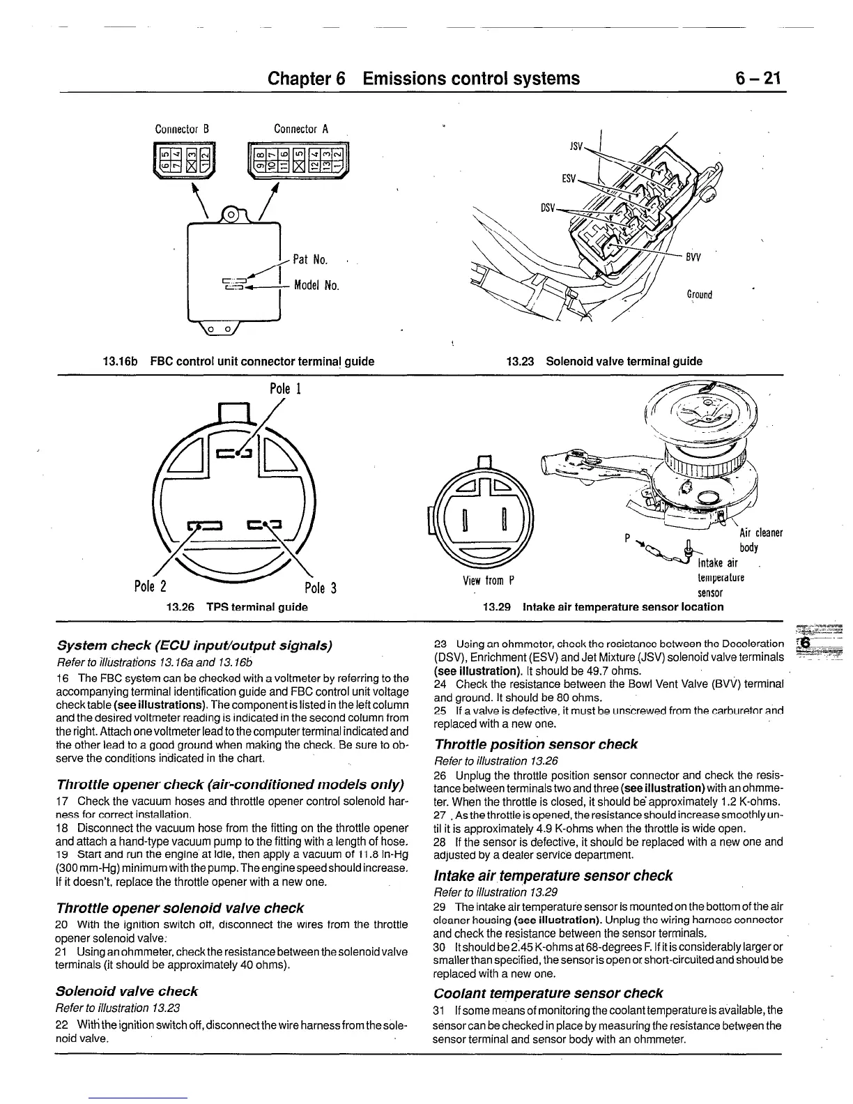
13.16b FBC control unit connector termina! guide 13.23 Solenoid valve terminal guide
Pole 1
Fj/
IV-----lb
Pole 2
View from P
‘Air cleaner
’ hR&take air body.
temperature
sensor
13.26 TPS terminal guide 13.29 Intake air temperature sensor location
System check (ECU input/output sighals)
Refer to illustrations 13.16a and 13.16b
16 The FBC system can be checked with a voltmeter by referring to the
accompanying terminal identification guide and FBC control unit voltage
check table (see illustrations). The component is listed in the left column
and the desired voltmeter reading is indicated in the second column from
the right. Attach onevoltmeter lead to the computer terminal indicated and
the other lead to a good ground when making the check. Be sure to ob-
serve the conditions indicated in the chart.
F-g --Fe
,lmcz-z
- ._
__.-
23 Using an ohmmeter, check the resistance between the Deceleration am
(DSV), Enrichment (ESV) and Jet Mixture (JSV) solenoid valve terminals -=I-? -:?I
(see illustration). It should be 49.7 ohms:
24 Check the resistance between the Bowl Vent Valve (BVV) terminal
and ground. It should be 80 ohms.
25 If a valve is defective, it must be unscrewed from the carburetor and
replaced with a new one.
Throttle opener check (air-conditioned models only)
17 Check the vacuum hoses and throttle opener control solenoid har-
ness for correct installation.
18 Disconnect the vacuum hose from the fitting on the throttle opener
and attach a hand-type vacuum pump to the fitting with a length of hose.
19 Start and run the engine at idle, then apply a vacuum of 11.8 in-Hg
(300 mm-Hg) minimum with the pump. Theenginespeedshouldincrease.
If it doesn’t, replace the throttle opener with a new one.
Throttle opener solenoid valve check
20 With the ignition switch off, disconnect the wires from the throttle
opener solenoid valve:
21 Using an ohmmeter, check the resistance between the solenoid valve
terminals (it should be approximately 40 ohms).
Throttle position sensor check
Refer to illustration 13.26
26 Unplug the throttle position sensor connector and check the resis-
tance between terminals two and three (see illustration) with an ohmme-
ter. When the throttle is closed, it should be approximately 1.2 K-ohms.
27 . As the throttle is opened, the resistance should increase smoothly un-
til it is approximately 4.9 K-ohms when the throttle is wide open.
28 If the sensor is defective, it should be replaced with a new one and
adjusted by a dealer service department.
Intake air temperature sensor check
Refer to illustration 13.29
29 The intake air temperature sensor is mounted on the bottom of the air
cleaner housing (see illustration). Unplug the wiring harness connector
and check the resistance between the sensor terminals.
30 It should be 2145 K-ohms at 68-degrees F. If it is considerably larger or
smallerthan specified, the sensor is open or short-circuited and should be
replaced with a new one.
Solenoid valve check
Coolant temperature sensor check
Refer to illustration 13.23
31 If some means of monitoring the coolant temperature is available, the
22 With the ignition switch off, disconnectthe wire harness from thesole-
sensor can be checked in place by measuring the resistance between the
noid valve.
sensor terminal and sensor body with an ohmmeter.
 Loading...