2A-6
Chapter 2 Part A 2.6L four-cylinder engine
5.7 Back off the adjusters until they only protrude 1 mm
(0.040 in)
IDENTlFlCATiON MARK (CENTER CAP ONLY)
(2: NO. 2, 3; NO. 3, 4: NO. 4)
ROCKER SHAFT,
ROCKER SHAFT,
RIGHT
LEFT
MATING MARK
ON THE SHAFT
MATING MARK
ON THE SHAFT
/ ARRbW
MATING MARK ’ INDlCATiNG MAilNG MARK
ON THE CAP THE FRONT ON THE CAP
5.8b Be sure the mating mark on the cap is aligned with the
mating mark on the shaft
arms, for scoring and excessive wear. Replace any parts that are dam-
aged or excessively worn. Also, make sure the oil holes in the shafts are
not plugged.
Installation
Refer to illustrations 5.7, 5.8a and 5.86
7 Loosen the locknutsand back off the adjusters until they only protrude
1 mm (0.040-inch) (see illustration).
8
Lubricate all components with assembly lube or engine oil and reas-
semble the shafts. When installing the rocker arms, shafts and springs,
note the markings and the difference between the left and right side parts
(see illustration). Place the marks in the end of the shaft directly in line
with the marks on the caps (see illustration) to keep them aligned until
they are ready to be installed onto the cylinder head.
9
Position the rocker arm assemblies on the cylinder head and install
the mounting bolts finger tight. Note: Check the numberedmarkings on
the caps to make sure the caps are in the correct numerical sequence.
10 Tighten the camshaft bearing cap bolts l/4-turn at a time, starting
from the middle and working out toward the ends, until the torque listed in
this Chapter’s Specifications is reached.
11
Adjust the valve clearances (cold) as described in Chapter 1.
12
Temporarily install the valve cover and run the engine until it is fully
warmed up.
13
Readjust the valves while the engine is still warm (see Chapter 1).
14
Reinstall the remaining parts in the reverse order of removal.
15 Run the engine and check for oil leaks and proper operation.
6 Valve springs, retainers and seals - replacement
Refer to illustrations 6.4, 6.9 and 6.17
Note 1: Broken valve springs and defective valve stem seals can be re-
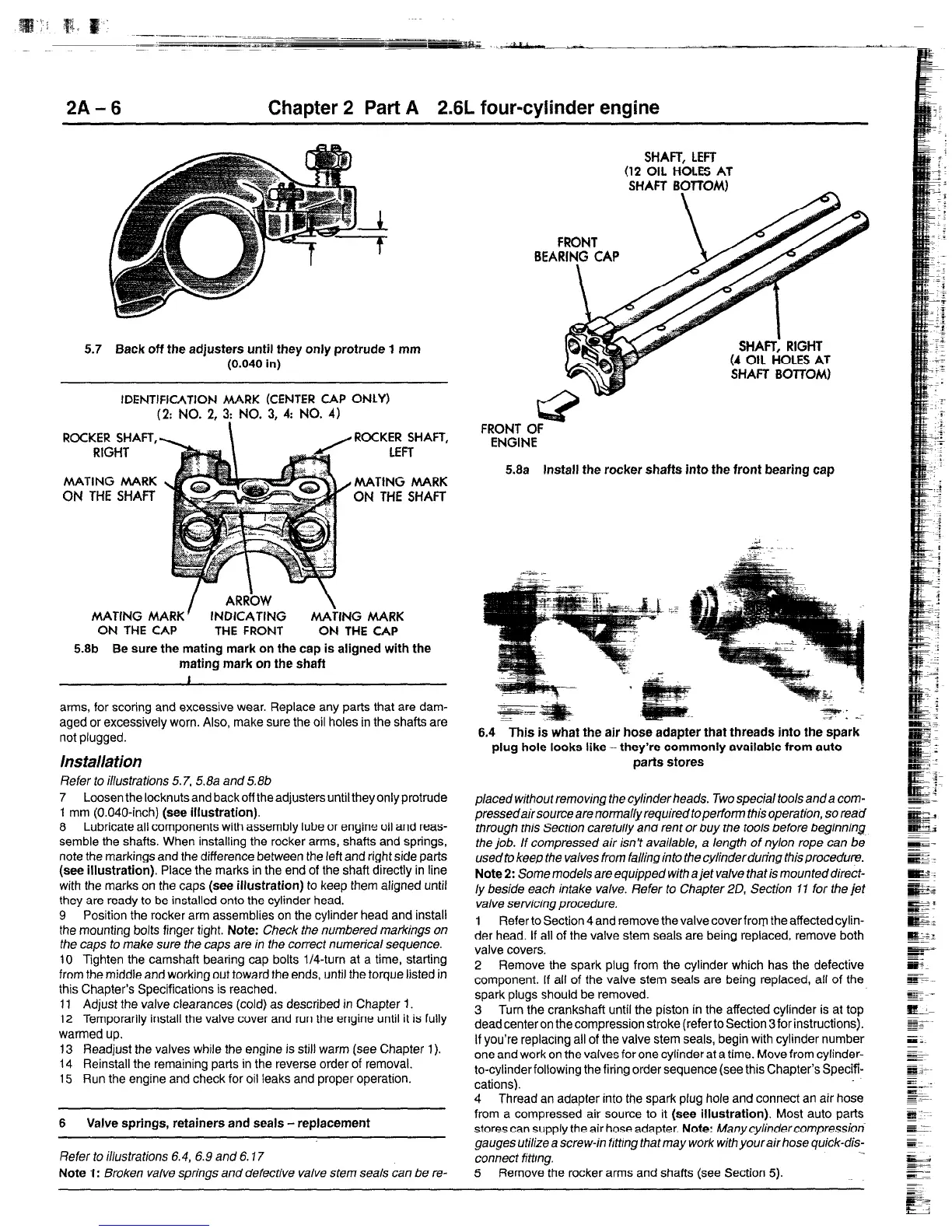
FRONT
OF
SHAFT, LEFT
(12 OIL HOLES AT
SHAFT BOTlO&t)
ENGINE
5.8a Install the rocker shafts into the front bearing cap
6.4 This is what the air hose adapter that threads into the spark
plug hole looks like -they’re commonly available from auto
parts stores
placed without removing the cylinder heads. Two special tools and a com-
pressedair source are normaffy required toperfonn this operation, so read
through this Section carefully and rent or buy the tools before beginning
the job. If compressed air isn’t available, a length of nyion rope can be
usedto keep the valves from falling into the cylinder during this procedure.
Note 2: Some models are equipped with a jet vatve that is mounted direct-
ly beside each intake valve. Refer to Chapter 20, Section 11 for the jet
valve servrcmngprocedure.
1 Refer to Section 4 and remove the valve cover from the affected cylin-
der head. If all of the valve stem seals are being replaced, remove both
valve covers.
2 Remove the spark plug from the cylinder which has the defective
component. If all of the valve stem seals are being replaced, all of the
spark plugs should be removed.
3 Turn the crankshaft until the piston in the affected cylinder is at top
dead center on the compression stroke (refer to Section 3 for instructions).
If you’re replacing all of the valve stem seals, begin with cylinder number
one and work on the valves for one cytinder at a time. Move from cylinder-
to-cylinder following the firing order sequence (see this Chapter’s Specif-
cations).
4 Thread an adapter into the spark plug hole and connect an air hose
from a compressed air source to it (see illustration). Most auto parts
stores can supply the air hose adapter. Note: Manycylindercompressiori
gauges utilize a screw-in fittrng that may work with your air hose quick-dis-
connect fittmg.
5 Remove the rocker arms and shafts (see Section 5).
 Loading...