1-18 Chapter 1 Tune-up and routine maintenance
No. of q a
/‘&,2
Front of -
tt 00
@) (9
cE3
G3
Intake valves
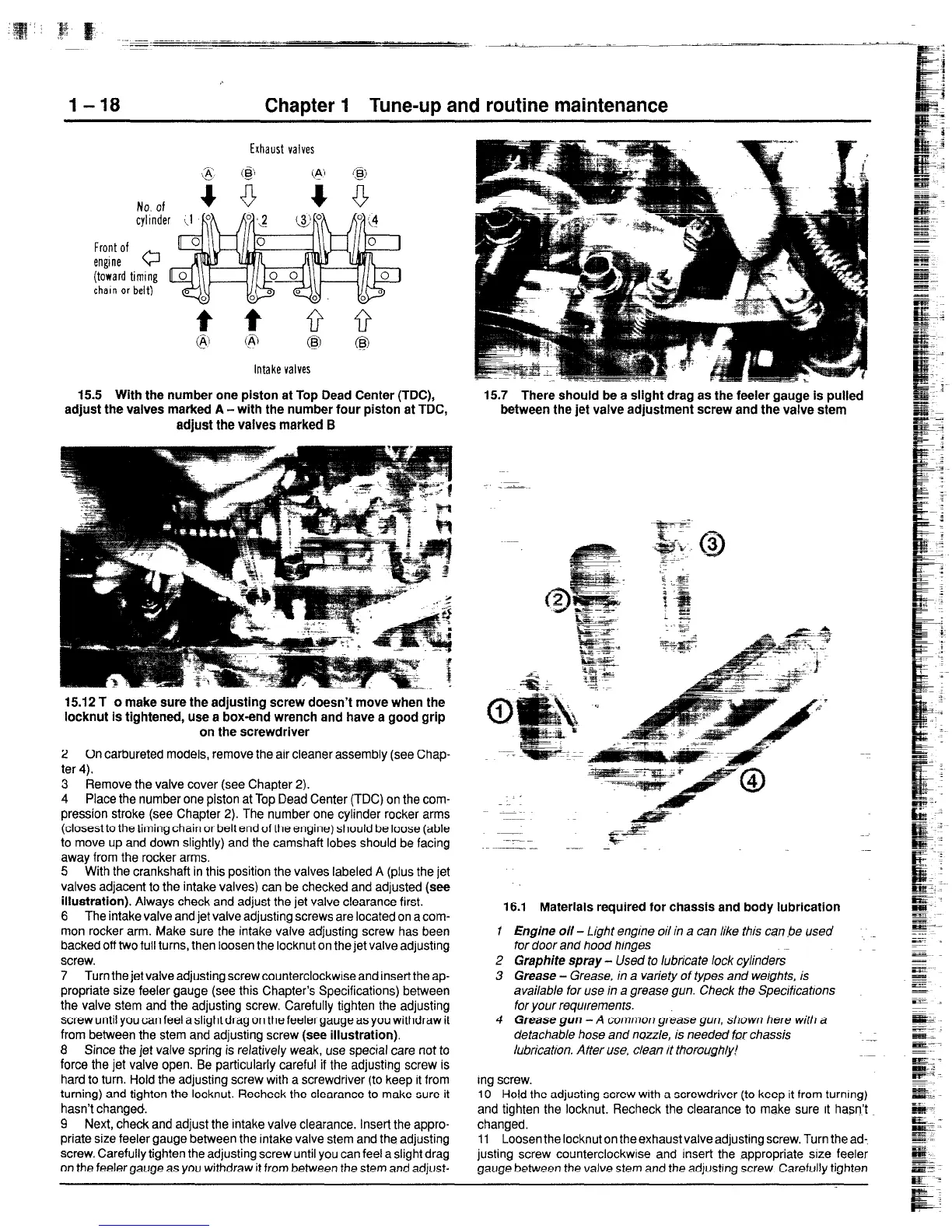
15.5 With the number one piston at Top Dead Center (TDC),
adjust the valves marked A-with the number four piston at TDC,
adjust the valves marked B
15.7 There should be a slight drag as the feeler gauge is pulled
between the jet valve adjustment screw and the valve stem
15.12 T o make sure the adjusting screw doesn’t move when the
locknut is tightened, use a box-end wrench and have a good grip
on the screwdriver
2 On carbureted models, remove the air cleaner assembly (see Chap-
ter 4).
3 Remove the valve cover (see Chapter 2).
4 Place the number one piston at Top Dead Center (TDC) on the com-
pression stroke (see Chapter 2). The number one cylinder rocker arms
(closest to the timing chain or belt end of the engine) should be loose (able
to move up and down slightly) and the camshaft lobes should be facing
away from the rocker arms.
5 With the crankshaft in this position the valves labeled A (plus the jet
valves adjacent to the intake valves) can be checked and adjusted (see
illustration).
Always check and adjust the jet valve clearance first.
6 The intake valve and jet valve adjusting screws are located on a com-
mon rocker arm. Make sure the intake valve adjusting screw has been
backed off two full turns, then loosen the locknut on the jet valve adjusting
screw.
7 Turn the jet valve adjusting screw counterclockwise and insert the ap-
propriate size feeler gauge (see this Chapter’s Specifications) between
the valve stem and the adjusting screw. Carefully tighten the adjusting
screw until you can feel a slight drag on the feeler gauge as you withdraw it
from between the stem and adjusting screw
(see illustration).
8 Since the jet valve spring is relatively weak, use special care not to
force the jet valve open. Be particularly careful if the adjusting screw is
hard to turn. Hold the adjusting screw with a screwdriver (to keep it from
turning) and tighten the locknut. Recheck the clearance to make sure it
hasn’t changed.
9 Next, check and adjust the intake valve clearance, Insert the appro-
priate size feeler gauge between the intake valve stem and the adjusting
screw. Carefully tighten the adjusting screw until you can feel a slight drag
on the feeler gauge as you withdraw it from between the stem and adjust-
16.1 Materials required for chassis and body lubrication
I Engine oil - Light engine oil in a can like this can be used
for door and hood hinges
2 Graphite spray - Used to lubricate lock cylinders
3 Grease - Grease, in a variety of types and weights, is
available for use in a grease gun. Check the Specificatrons
for your requlremenrs.
4 Grease gun - A common grease gun, shown here with a
detachable hose and nozzle, is needed for chassis
lubrication. After use. clean it thoroughly!
ing screw.
10 Hold the adjusting screw with a screwdriver (to keep it from turnmg)
and tighten the locknut. Recheck the clearance to make sure It hasn’t
changed.
11 Loosen the locknut on the exhaust valve adjusting screw. Turn the ad-,
justing screw counterclockwise and insert the appropriate size feeler
gauge between the valve stem and the adjusting screw. Carefully tighten
 Loading...