Chapter 5 Engine electrical systems
5-9
SCREWDRIVER
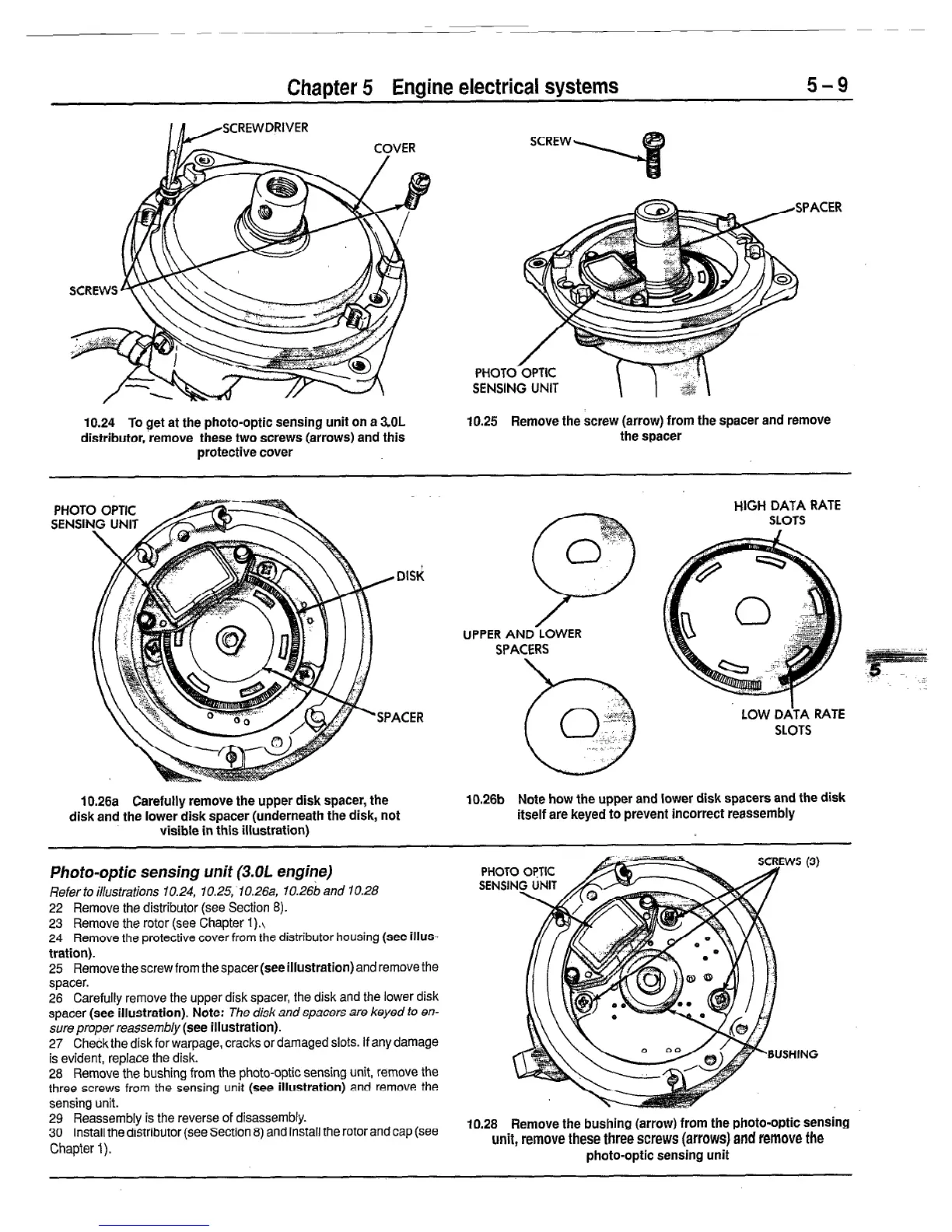
10.24 To get at the photo-optic sensing unit on a 3.OL
distributor,‘remove these two screws (arrows) and this
protective cover
SCREW
‘ACER
PHOTO’
SENSING UNIT \
10.25 Remove the screw (arrow) from the spacer and remove
the spacer
PHOT
SENSI
UPPER AND LOWER
SPACERS
HIGH DATA RATE
SLOTS
LOW DATA RATE
SLOTS
10.26a Carefully remove the upper disk spacer, the
disk and the lower disk spacer (underneath the disk, not
visible in this illustration)
10.26b Note how the upper and lower disk spacers and the disk
itself are keyed to prevent incorrect reassembly
Photo-optic sensing unit (3.01 engine)
Refer to illustrations 10.24, 10.25;10.26a, IO.266 and 10.28
22 Remove the distributor (see Section 8).
23 Remove the rotor (see Chapter I).,
24 Remove the protective cover from the distributor housing
(see illus-
tration).
25 Remove the screw from the spacer
(see illustration)
and remove the
spacer.
26 Carefully remove the upper disk spacer, the disk and the lower disk
spacer
(see illustration). Note: The
disk and spacers are keyed to en-
sure proper reassembly
(see illustration).
27 Check the disk for warpage, cracks or damaged slots. If any damage
is evident, replace the disk.
28 Remove the bushing from the photo-optic sensing unit, remove the
three screws from the sensing unit
(see illustration)
and remove the
sensing unit.
29 Reassembly is the reverse of disassembly.
30 Install the distributor (see Section 8) and install the rotor and cap (see
Chapter 1).
10.28 Remove the bushing (arrow) from the photo-optic SenSing
unit, remove these three screws (arrows) and remove the
photo-optic sensing unit
 Loading...