Chapter 2 Part C
3.OL V6 engine
10.13 Be sure to mark each bolt with the correct size and
location for proper reassembly
7
Remove the cooling fan and clutch assembly (see Chapter 3).
8 Position the number one piston at TDC on the compression stroke
(see Section 3). Remove the spark plugs (see Chapter 1).
9
Remove the drivebelts (see Chapter 1)
(see illustration).
10 Remove the power steering pump (see Chapter IO) without discon-
necting the lines. Also remove the power steering pump bracket and the
belt tensioner bracket.
11 Remove the air conditioning compressor (see Chapter 3) bracket
and idler pulley
(see illustration
10.9). Do not disconnect the refrigerant
lines from the compressor. Remove the cooling fan bracket assembly.
12 Remove the crankshaft pulley (see Section 9), the vibration damper
and crankshaft sprocket flange.
Note: Don’t allow the crankshaft to rotate
during removalof the pulley If the crankshaft moves, the number onepis-
ton will no longer be at TDC.
13 Remove the bolts securing the timing, belt upper and lower covers
(see illustration).
Note the various type and sizes of bolts by recording a
diagram or making specific notes while the timing belt cover is being re-
moved. The bolts must be reinstalled in their original locations.
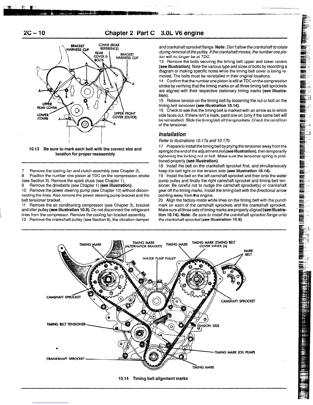
14 Confirm that the number one piston is still at TDC on the compression
stroke by verifying that the timing marks on all three timing belt sprockets
are aligned with their respective stationary timing marks
(see illustra-
tion).
15 Relieve tension on the timing belt by loosening the nut or bolt on the
timing belt tensioner
(see illustration 10.14).
16 Check to see that the timing belt is marked with an arrow as to which
side faces out. If there isn’t a mark, paint one on (only if the same belt win
be reinstalled). Slide the timing belt off the sprockets. Check the condition
of the tensioner.
Installation
Refer to illustrations 10.7 7a and 10.1 ?b
17 Prepare to install the timing belt by prying the tensioner away from the
springto the end of the adjustment slot
(see illustration),
then temporarily
tightening the locking nut or bolt. Make sure the tensioner spring is posi-
tioned properly
(see illustration).
18 Install the belt on the crankshaft sprocket first, and simultaneously
keep the belt tight on the tension side
(see illustration 10.14).
19 Install the belt on the left camshaft sprocket and then onto the water
pump pulley and finally the right camshaft sprocket and timing belt ten-
sioner. Be careful not to nudge the camshaft sprocket(s) or crankshaft
gear off the timing marks. Install the timing belt with the directional arrow
pointing away from ihe engine.
20 Align the factory-made white lines on the timing beft with the punch
mark on each of the camshaft sprockets and the crankshaft sprocket.
Make sure all three sets of timing marks are properly aligned
(see Illustra-
tlon 10.14). Note: Be sure to install the crankshaft sprocket flange onto
the crankshaff sprocket (see illustration 10.9).
TIMING MARK
-
n”‘NG \““”
TIMING MARK (TIMING BELT
COVER INNER (4
llMNG BELT TENSIONER-,
>Y
CRANKSHAFT SPROCKET-A
SON SIDE
TIMING MARK (OIL PUMP)
10.14 Timing belt alignment marks
 Loading...