7-17
Chapter 7 ASSEMBLY OF BASIC ENGINE
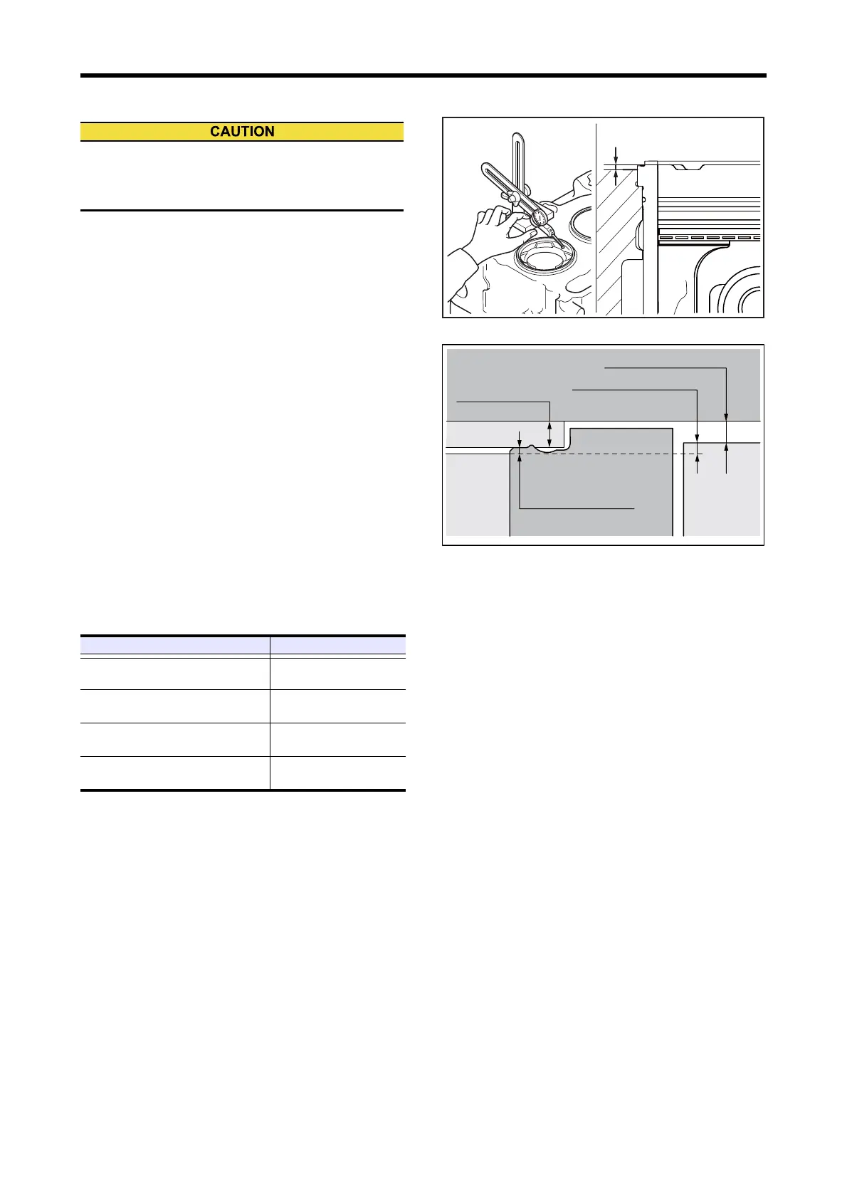
2.14 Piston Protrusion - Measure
Measure the protrusion of each piston, following the
instructions below. If the value exceeds the limit, inspect the
clearances between various parts involved.
(1) Move the piston to the top dead center.
(2) Apply the dial gauge probe to the top face of crankcase,
and adjust the dial gauge to zero.
(3) Move the dial gauge to the top face of piston, measure
the maximum protrusion by turning the crankshaft near
top dead center.
Note: The crankshaft position that indicates the maximum
protrusion is defined as the correct top dead center.
(4) Measure the protrusion at four places on the piston top
face, and calculate the mean value.
Note: The top clearance (clearance between the piston top
and cylinder head) can be calculated by the piston pro-
trusion, cylinder liner flange protrusion and cylinder
head gasket thickness.
Top clearance = Cylinder head gasket thickness + Cyl-
inder liner flange protrusion - Piston protrusion
Piston Protrusion - Measure
Top clearance
Piston protrusion must always meet the standard, as
the amount of protrusion not only influences engine
performance, but it also prevents valve from stamping.
Item Standard value
Piston protrusion
0.04 to 0.64 mm
[0,0016 to 0.0252 in.]
Cylinder liner flange protrusion
0.11 to 0.20 mm
[0.0043 to 0.0079 in.]
Thickness of cylinder head gasket
1.77 to 1.83 mm
[0.0697 to 0.0720 in.]
Top clearance
1.24 to 1.99 mm
[0.0488 to 0.0783 in.]
Cylinder headCylinder head
Cylinder linerCylinder liner
Cylinder liner
Cylinder liner flange
Cylinder liner flange
protrusionprotrusion
Cylinder liner flange
protrusion
CrankcaseCrankcaseCrankcase
Piston protrusion
Piston protrusionPiston protrusion
Top clearance
Top clearance
Top clearance
Cylinder head gasket
Cylinder head gasket
thickness thickness
Cylinder head gasket
thickness
Cylinder head
PistonPiston
Piston
 Loading...