FPΣ
High-speed Counter and Pulse Output Functions
6-56
6.5 PWM Output Function
This section explains about the PWM output function of FPΣ.
6.5.1 Overview of PWM Output Function
PWM output function
With the F173 (PWMH) instruction, the pulse width modulation output of specified duty
ratio is obtained.
Setting the system register
When using the PWM output function, set the channels “CH0 and CH2” corresponding
to system registers 400 and 401 to “Do not use high-speed counter.”
6.5.2 Instruction Used with PWM Output Function
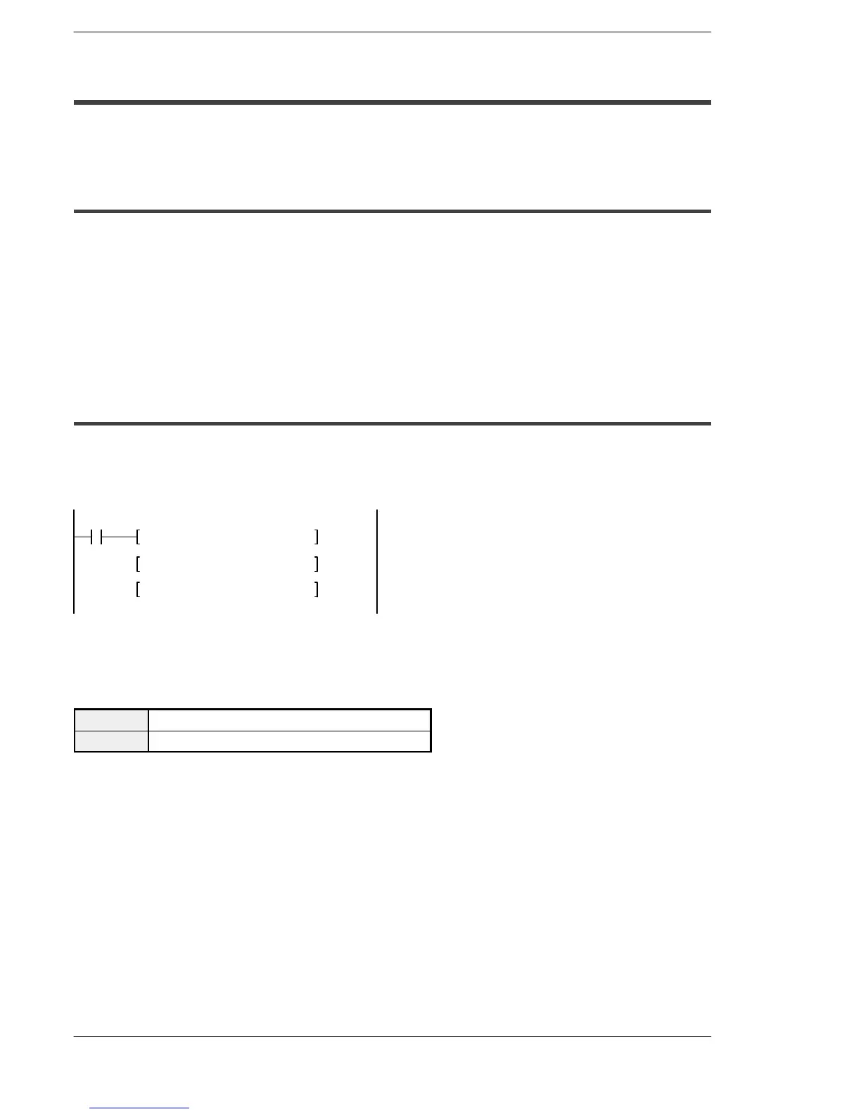
PWM output instruction (F173)
While X6 is in the on state, a pulse with a period of 502.5ms and duty ratio of 50% is
output from Y0 of specified channel “CH2”.
X6
F0 MV, K1, DT100
F0 MV, K500, DT101
F173 PWMH, DT100, K0
Figure 126: FPΣ PWM output instruction “F173” (program)
When the program is run, the data table will be as shown below.
Data table
DT100 Control code * 1:K1
DT101 Duty *2 :50%