FPΣ
Communication Function 1 Computer Link
8-22
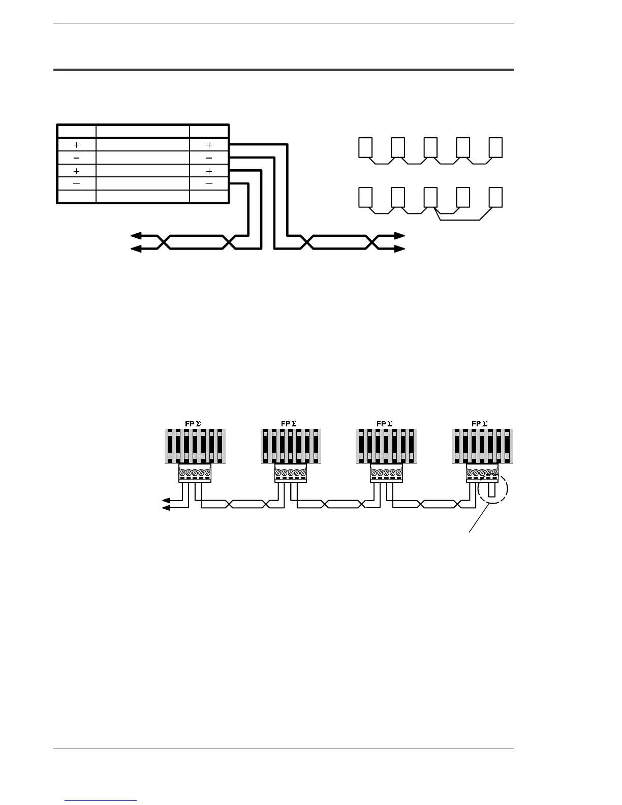
8.3.4 Connection with External Device
Connection diagram
Pin name
Signal name Abbre.
FPΣ side (5-pin)
Wiring should extend from one unit to the next.
Never run two wires from the same unit to two
other units.
Correct
wiring
Incorrect
wiring
Transmission line 1 (+)
Transmission line 1 (–)
Transmission line 2 (+)
Transmission line 2 (–)
Terminal station setting
To external device
with RS485 port
To external device
with RS485 port
EE
Figure 160: FPΣ Computer link - connection diagram
With 1 : N communication, the various RS485 devices are connected using twisted pair
cables. The (+) and (–) signals of transmission line 1 and transmission line 2 are
connected inside the communication cassette, and either port may be used as COM.1
port.
Setting of terminal station
In the PLC that serves as the final unit (terminal station), the transmission line (–) and
the E terminal should be shorted.
To C-NET adapter of
computer connection
Short the transmission line (–) and the E
terminalin the final unit (terminal station).
Transmission line Transmission line
Transmission line
Figure 161: FPΣ Computer link - terminal station setting

 Loading...

