FPΣ
5.2 Wiring of Power Supply
5-11
5.2.2 Grounding
Under normal conditions, the inherent noise resistance is sufficient. However, in
situations of excess noise, ground the instrument to increase noise suppression.
For grounding purposes, use wiring with a minimum of 2 mm
2
. The grounding
connection should have a resistance of less than 100 Ω.
The point of grounding should be as close to the PLC unit as possible. The ground wire
should be as short as possible.
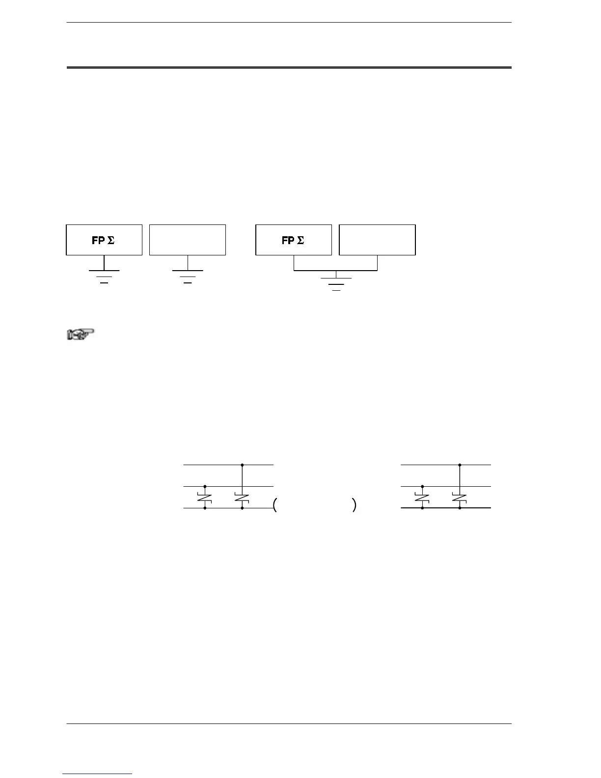
If two devices share a single ground point, it may produce an adverse effect. Always
use an exclusive ground for each device.
Other device
(Inverter etc.)
CORRECT INCORRECT
Other device
(Inverter etc.)
Figure 37: FPΣ Grounding
Note
Depending on the surroundings in which the equipment is used,
grounding may cause problems.
Example:
Since the power supply line of the FPΣ power supply connector
is connected to the function earth through a varistor, if there is
an irregular potential between the power supply line and earth,
the varistor may be shorted.
24 V DC
0V
Function
earth
Varistor
FPΣ power supply line
24 V DC
0V
Function
earth
Varistor
(39 V)
FP0exponsionunit
power supply line
82 V: for C32T, C32T2
56 V: for C24R2
Figure 38: Power supply line of FPΣ and FP0 expansion unit

 Loading...

