FPΣ
2.2 Input and Output Specifications
2-7
2.2 Input and Output Specifications
This section contains input and output specifications of FPΣ control unit.
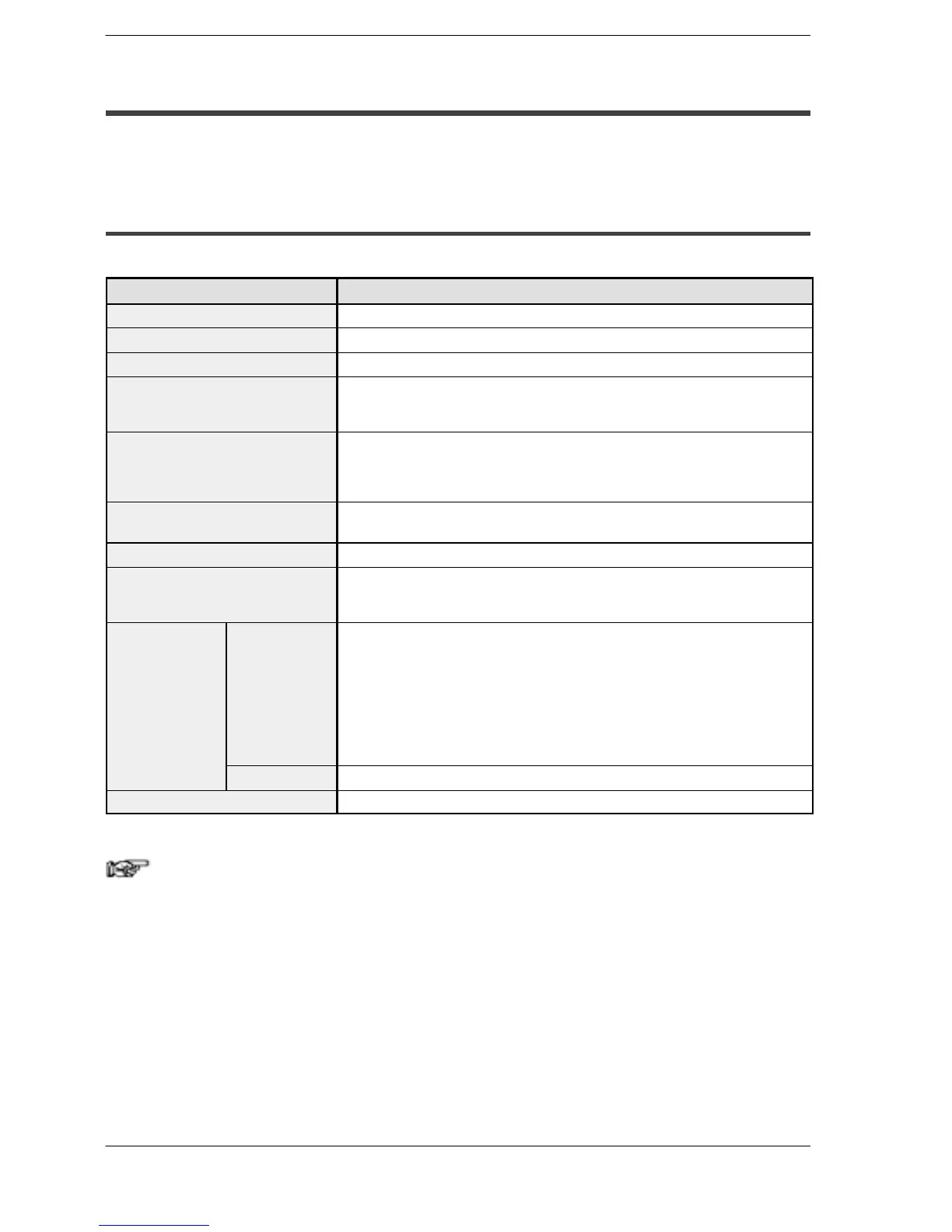
2.2.1 Input Specifications
Input specifications (for all type)
Item Description
Insulation method
Optical coupler
Rated input voltage
24 V DC
Operating voltage range
21.6 to 26.4 V DC
Rated input current
For X0, X1, X3, X4:approx. 8 mA
For X2, X5 to X7: approx. 4.3 mA
For X8 to XF: approx. 3.5 mA
Input points per common
For C32T, C32T2: 16 points/common
For C24R2: 8 points/common
(Either the positive or negative of the input power supply can be connected to
common terminal.)
Min. on voltage/Min. on current
For X0, X1, X3, X4:19.2 V DC/6 mA
For X2, X5 to XF: 19.2 V DC/3 mA
Max. off voltage/Max. off current
2.4 V DC/1.3 mA
Input impedance
For X0, X1, X3, X4:3 kΩ
For X2, X5 to X7: 5.6 kΩ
For X8 to XF: 6.8 kΩ
Response time off → on
For input X0, X1, X3, X4:
1 ms or less: normal input
5 µs or less: high-speed counter, pulse catch, interrupt input settings
For input X2, X5 to X7:
1 ms or less: normal input
100 µs or less: high-speed counter, pulse catch, interrupt input settings
For input X8 to XF:
1 ms or less: normal input only
on → off
Same as above
Operating mode indicator
LED display
Note
X0 through X7 are inputs for the high-speed counter and have a
fast response time. If used as normal inputs, we recommend
inserting a timer in the ladder program as chattering and noise
may be interpreted as an input signal.
Also, the above specifications apply when the rated input voltage
is 24 VDC and the temperature is 25
°
C/70
°
F.

 Loading...

