FPΣ
Communication Function 3 PLC Link Function
10 - 18
10.4 Connection Example of PLC Link
This section explains about the connection example of PLC link.
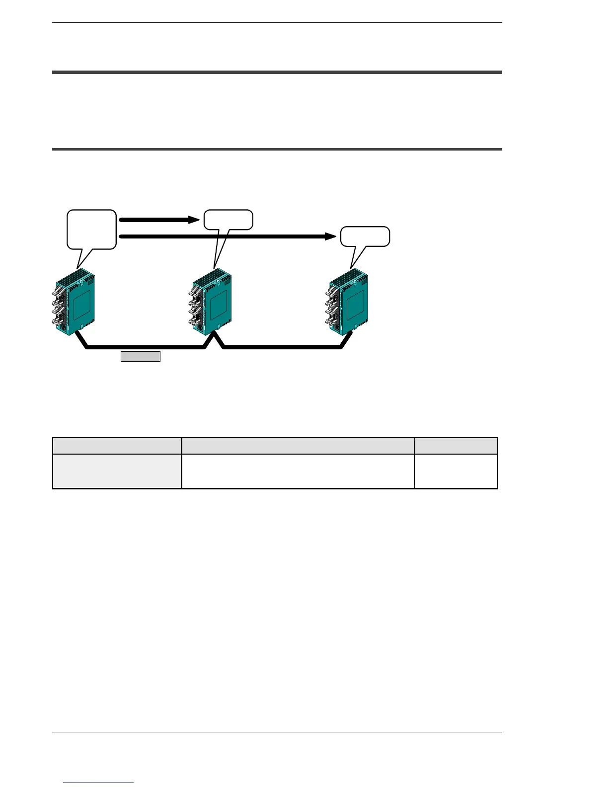
10.4.1 Using a PLC Link with Three FPΣ Units
In the example shown here, link relays are used, and when X1 of the control unit of unit
No. 1 goes on, Y0 of the control unit of unit No. 2 goes on. When X2 of the control unit
of unit No. 1 goes on, Y0 of the control unit of unit No. 3 goes on.
X1: on
X2: on
Y0: on
Y0: on
Link relay L0 turns on
Link relay L1 turns on
FPΣ
(Unit No. 1)
FPΣ
(Unit No. 2)
FPΣ
(Unit No. 3)
RS485
Figure 216: FPΣ Connection when using a PLC link with three FPΣ units
Communication cassettes used with the PLC link
Thefollowing typesof communicationcassettes canbe used with thePLC link function.
Name Description Part No.
FPΣ Communication cassette
1-channel RS485 type
This communication cassette is a 1-channel unit with a two-
wire RS485 port. It supports 1 : N computer links (C-NET),
general-purpose serial communication, and a PLC link.
FPG-COM3

 Loading...

