FPΣ
5.3 Wiring of Input and Output
5-15
5.3.2 Output Wiring
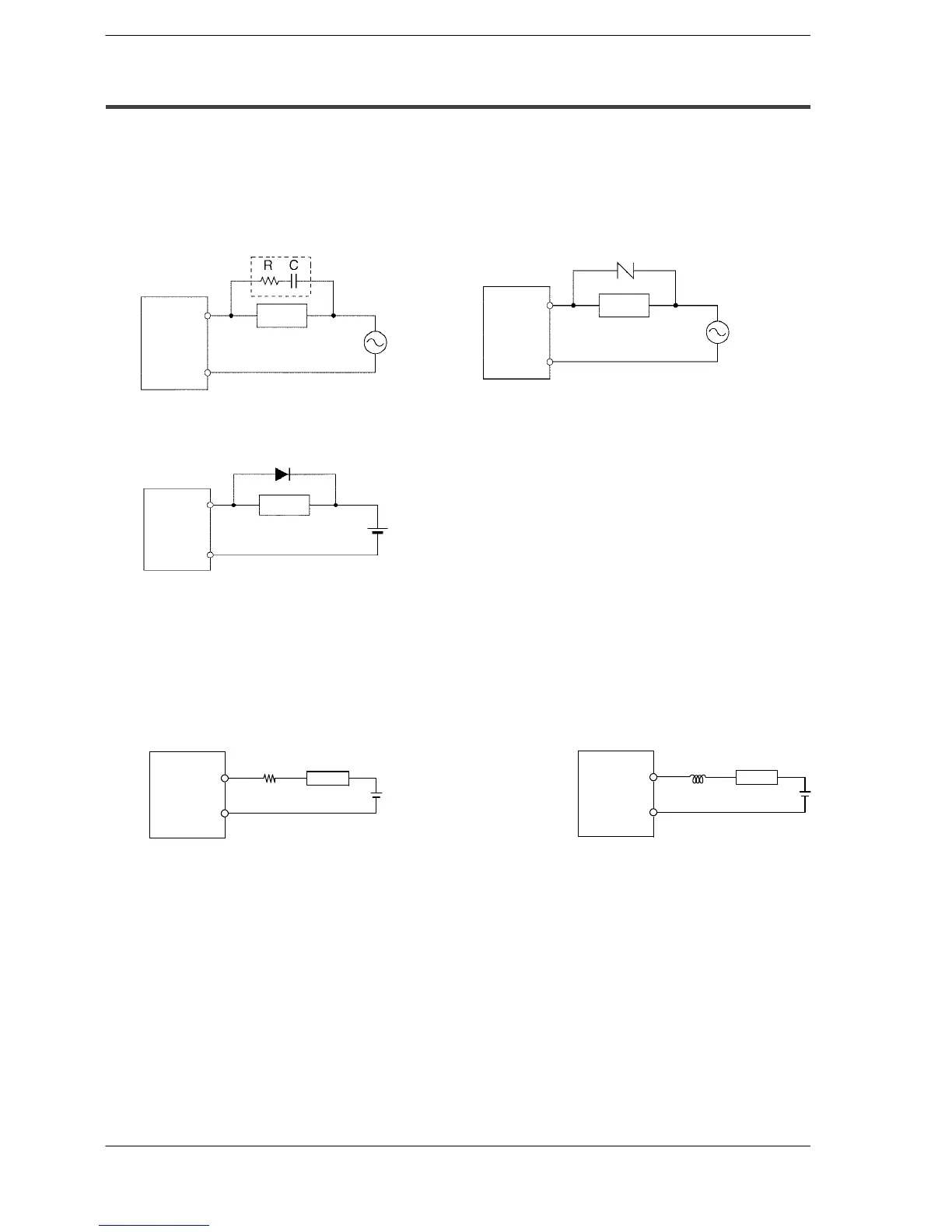
Protective circuit for inductive loads
With an inductive load, a protective circuit should be installed in parallel with the load.
When switching DC inductive loads with relay output type, be sure to connect a diode
across the ends of the load.
When using an AC inductive load
COM
Output
terminal
Varistor
FPΣ
Load
When using a DC inductive load
FPΣ
Reverse voltage (V
R
): 3 times the load voltage
Average rectified forward current (I
0
): Load current or more
Diode:
COM
Output
terminal
Diode
Load
Precautions when using capacitive loads
When connecting loads with large in-rush currents, to minimize their effect, connect a
protection circuit as shown below.
Load
Resistor
Output
terminal
COM
Load
Inductor
Output
terminal
COM
FP
Σ
FP
Σ
Figure 46: FPΣ Precautions when using capacitive loads
About the short-circuit protective circuit
To prevent the output circuit from being damaged by a short-circuit or other electrical
problems on the output side, a transistor with short-circuit protection is provided.
Example of surge absorber: R: 50 Ω, C: 0.47 μF
FPΣ
COM
Output
terminal
Surge absorver
Load

 Loading...

