FPΣ
High-speed Counter and Pulse Output Functions
6-16
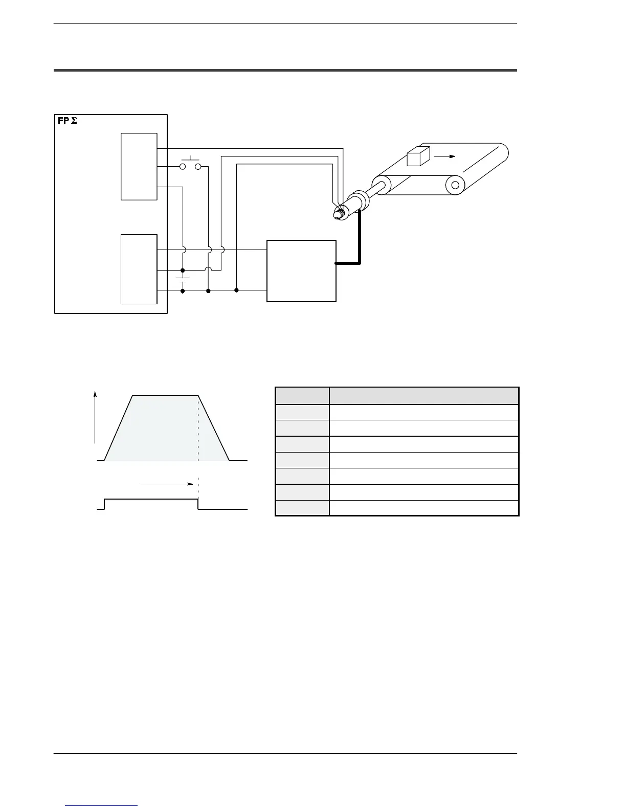
6.3.6 Sample Program
Positioning operations with a single speed inverter
Y0
+
–
X0
X5
COM
Encoder input
Operation start
Input terminal
Output terminal
Inverter operation
Encoder
Motor
Operation/Stop
Inverter
COM
Conveyor
Wiring example
Figure 78: FPΣ High-speed counter function - sample program 1 (wiring)
I/O No. Description
X0
Encoder input
X5
Operation start signal
Y0
Inverter operation signal
R100
Positioning operation running
R101
Positioning operation start
R102
Positioning done pulse
R903A
High-speed counter CH0 control flag
Figure 79: FPΣ High-speed counter function - sample program 1 (operation chart)
Y0
Speed
Number of pulse
50000
Operation chart I/O allocation

 Loading...

