FPΣ
High-speed Counter and Pulse Output Functions
6-12
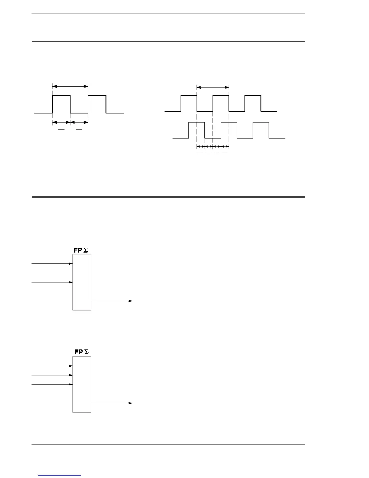
6.3.3 Min. Input Pulse Width
The minimum input pulse width indicated below is necessary for the period
T (1/frequency).
T
T
2
T
2
Single phase
T
4
T
T
4
T
4
T
4
Two-phase
Figure 67: FPΣ High-speed counter function
- min. input pulse width (single phase)
Figure 68: FPΣ High-speed counter function
- min. input pulse width (two-phase)
6.3.4 I/O Allocation
The inputting and outputting, as shown in the table on page 6 - 5, will differ depending
on the channel number being used.
Theoutput turned on and off can be specified from Y0 to Y7 asdesired with instructions
F166 (HC1S)
and
F167 (HC1R)
.
X0
X2
Yn
*
Count input
Reset input
On and off output
When using CH0 with incremental input and reset input
* The output turned on and off when the target values match can be specified from Y0
to Y7 as desired.
Figure 69: FPΣ High-speed counter function - I/O allocation-1
X0
X2
A phase input
Reset input
Yn
*
On and off output
X1
B phase input
When using CH0 with two-phase input and reset input
* The output turned on and off when the target values match can be specified from Y0 to Y7
as desired.
Figure 70: FPΣ High-speed counter function - I/O allocation-2

 Loading...

