FPΣ
Specifications and Functions of Control Unit
2-12
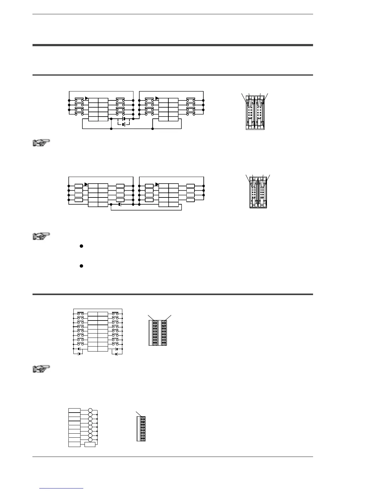
2.3 Terminal Layout Diagram
2.3.1 Control Unit (for C32T and C32T2)
Input
X0-7
COM
X5
X7
X1
X3
COM
X4
X6
X0
X2
COM
XD
XF
X9
XB
COM
XC
XE
X8
XA
X0 X1
X8-F
X8 X9
Note
The four COM terminals of input circuit are connected internally.
Output
Y5
Y7
Y1
Y3
(+)
Y4
Y6
Y0
Y2
L
L
L
L
L
L
L
L
YD
YF
Y9
YB
(+)
YC
YE
Y8
YA
L
L
L
L
L
L
L
L
Y0
Y1
Y9
Y8
(–)
Y0-7 Y8-F
(–)
(Connector front view)
Figure 17: FPΣ Terminal layout diagram (I/O connector)
Notes
The two (+) terminals of output circuit are connected
internally.
The two (–) terminals of output circuit are connected internally.
2.3.2 Control Unit (for C24R2)
Input
X0 X8
COM
X5
X7
X1
X3
COM
XD
XF
X9
XB
XC
XE
X8
XA
X4
X6
X0
X2
Note
The two COM terminals of input circuit are not connected
internally.
Output
Y0
Y5
Y7
Y1
Y3
Y4
Y6
Y0
Y2
COM
L
L
L
L
L
L
L
L
Power
(Connector front view)

 Loading...

