16Service Manual – SC6000
04 - Control System
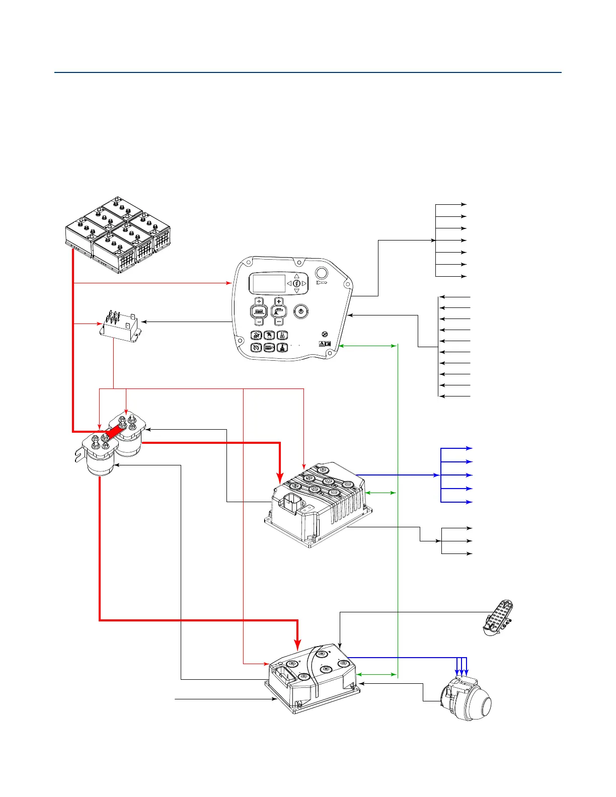
Functional Description
Within the SC6000 system there are three primary controllers: the Main Machine Controller (E2), the
Power Module (E3), and the Wheel Drive controller (E4). The three modules communicate with one another
via a CAN Bus (Controller Area Network).This permits each of the modules to perform their separate
functions, while still functioning as a complete system. (There is also a second, separate CAN Bus between
the Main Machine Controller and the optional TrackClean Module.)
Functional Block Diagram
E2 Main Control Board
E3 Power Module
E4 Wheel Drive Controller
K1 KSI Relay
K2 Relay
Enable
Control
K3 Relay
Control
Control
Power
Power
CAN Bus
Solution Solenoid
Dust Guard Solenoid
Horn
Backup Alarm
Headlight
Detergent Pump 1
Detergent Pump 2
Solution Level Sensors
Horn Switch
Burst of Power
Solution Switch
Float Switch
Side Broom Up Sensor
Seat Switch
E-Stop Switch
Charger Interlock
iButton
Squeegee Actuator
Deck Actuator
Option Pump
Vacuum Motor 2
Vacuum Motor 1
Side Sweep Motor
Brush Motor 2
Brush Motor 1
PWM
3Ø PWM
Temp/Pos
Feedback
Foot Pedal
Main Battery Power
Wheel Motor
Enable
Enable
E-Stop Switch

 Loading...