54Service Manual – SC6000 20 - Wheel System, Traction
Removal and Installation
Drive Controller
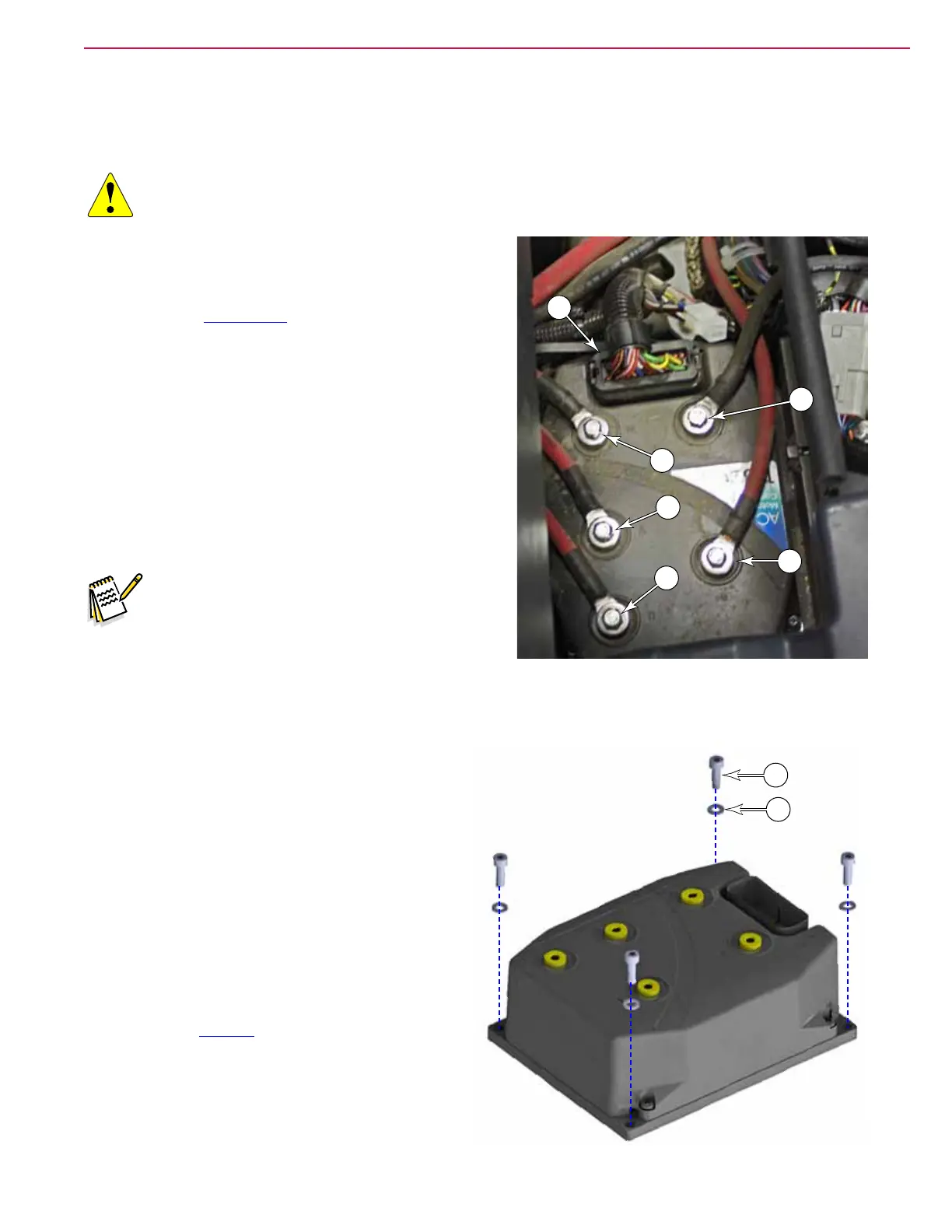
WARNING: Components below the oor cover contain high energy battery power. Disconnect the
battery connector before servicing machine.
1. Turn off the machine and disconnect the main battery
connector.
2. Remove the Floor Panel described on page 71.
3. Disconnect the logic cable connector (A) from the drive
controller.
4. Remove the M6 screw that secures the K3 relay
battery power wire (F), and remove the wire, at
washer, and lock washer.
5. Remove the battery negative power wire (E).
6. Label the 3 motor phase wires (B,C,D) with U, V, W,
and then remove them from the controller (with at
washer and lock washer).
Note: If any of the wires are reversed during
replacement, the drive motor will rotate
backward and operate loudly as the motor
windings conict with one another. The
drive controller will also likely issue an
encoder fault because the encoder will
provide unexpected results.
7. Remove the 4 screws (G) and washers (H) from
the outer corners of the module (not the 4 inner
screws) that secure the module to the machine
frame, and remove the module.
Replacement Notes
• When replacing the wire lugs, torque the screws
to 90 lb•in (10 N•m). Don’t forget the at and lock
washers.
• It may not be necessary to complete the drive
pedal calibration, but it is a good idea to at least
check the voltage of the neutral position as
described on page 53.
• After replacement, test the machine drive
functions in an open area to ensure proper
operation.
F
E
A
B
C
D
G
H

 Loading...