24Service Manual – SC6000 04 - Control System
CAN Bus Communication
CAN Bus communication was originally created for the automotive industry to allow distributed modules
(Nodes) throughout the vehicle to communicate with each other over a single serial channel without any
single Node being the Master of the communication channel. This means that each module broadcasts
what it has to say, and all other modules on the CAN Bus see the message, but pay attention only to those
messages they need to know about.
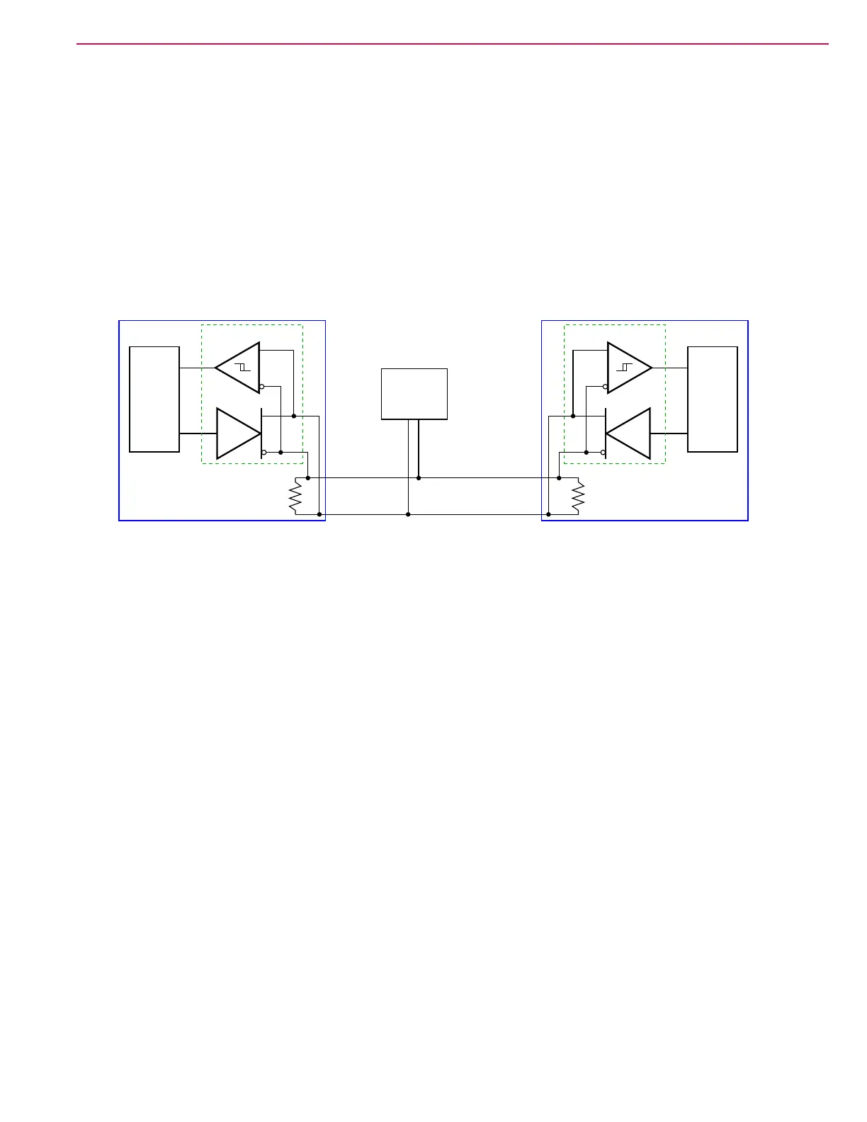
The CAN bus is a twisted-pair of wires running between all of the modules, with one wire being low and the
other wire high, voltage-wise. To send a data bit, the module pulls the high and low wires apart, voltage-
wise. All of the other modules monitor this to detect a communication message, which is a string of low and
high binary pulses. However, the binary logic states are reverse of typical, in that a logic-1 is recessive, and
the difference between CAN
H
and CAN
L
is low (near zero). A logic-0 is the dominant bit, and the difference
between CAN
H
and CAN
L
is high (approximately 2.5 volts).
RX
TX
120 Ω 120 Ω
CAN-L
CAN-H
Controller
CAN Bus
Transceiver
RX
TX
Controller
Transceiver
x-Number of
Additional
Modules
Because none of the modules represent the Master of the bus system, any of the modules can initiate a bus
transmission any time there is not already trafc on the bus. When the module detects inactivity on the bus,
it transmits a dominate bit, and begins sending the message priority level bits. But at the same time, it is
also monitoring the bus itself to detect if a higher priority message was being initiated at the same time.
The message with the higher priority level will have the bus high for the longest period, and therefore, that
module knows that it is sending the highest priority message. The other module ceases its transmission and
waits until the bus is available again.
Most CAN Bus messages originate from the Main Controller, or in response to a request from the Main
Controller. However, each module can send any emergency messages at any time. Below are typical message
sequences for the SC6000 machine.
• Every 250ms, the Main Controller broadcasts the PWM Requested values for the Right Brush, Squeegee
Actuator, Deck Actuator, and Option Pump.
• In response, the Power Module broadcasts the actual current ow for each of the above motors.
• Every 250ms, the Main Controller broadcasts the PWM Requested values for the Left Brush, Side Sweep,
Vacuum 1, and Vacuum 2.
• In response, the Power Module broadcasts the actual current ow for each of the above motors.
• Every 500ms, the Main Controller requests the actual (output) PWM for each of the motors listed above.
• In response, the Power Module broadcasts the actual PWM for each of the above motors.
• Every 100ms, the Main Controller broadcasts drive enable and speed limit messages, and a request for
drive status.
• In response, the Drive Module broadcasts the vehicle speed, motor temperature, motor RPM, throttle
command, throttle pot voltage, and motor current.
• Every 200ms, the Main Controller requests various Drive Controller parameters.
• In response, the Drive Module broadcasts interlock, E-stop, phase A and B encoder position, drive
controller temperature, and temperature cutback %.

 Loading...