17Service Manual – SC6000 04 - Control System
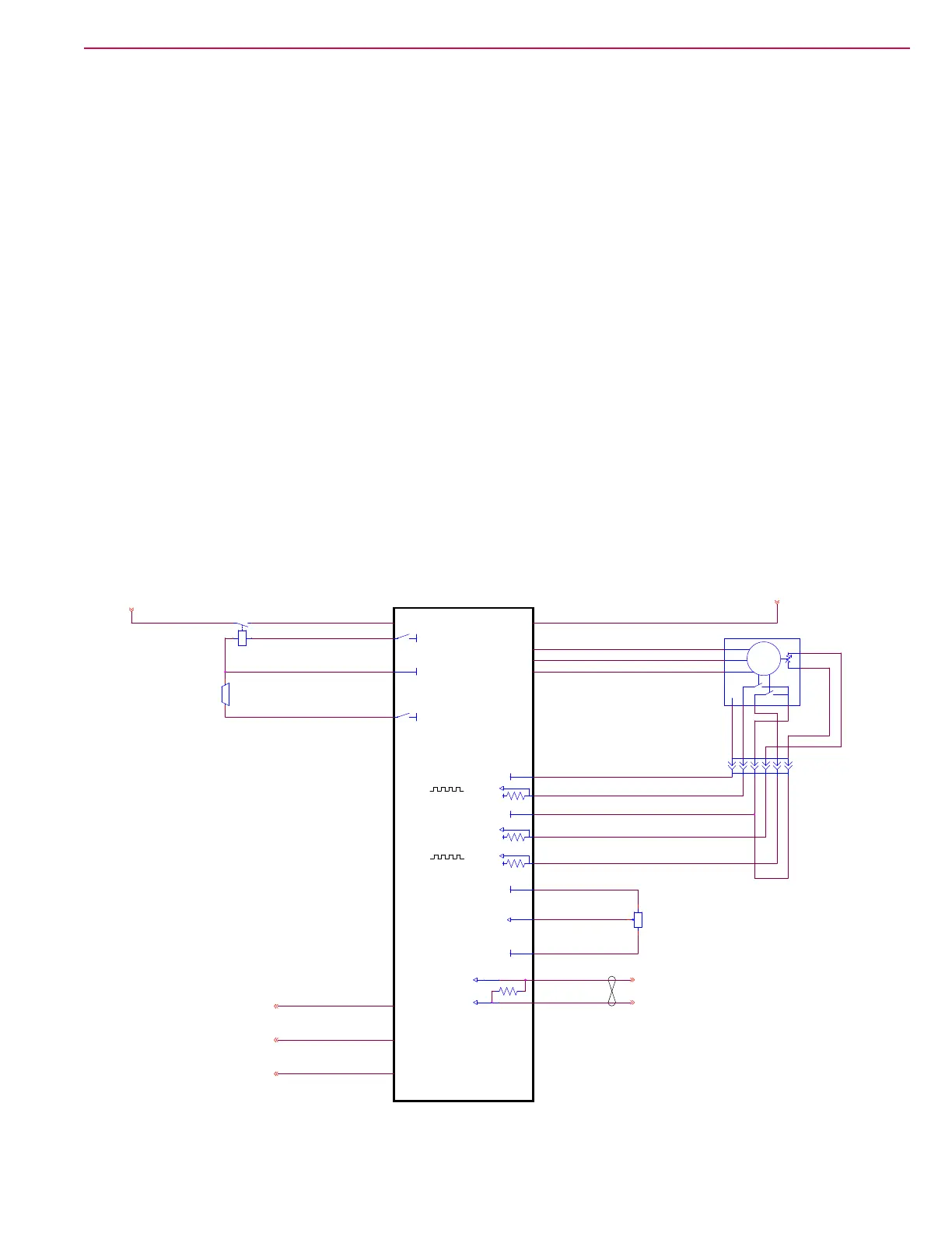
Wheel Drive Controller
The wheel drive controller operates and monitors the wheel motor. It generates a 3-phase Pulse Width
Modulated (PWM) power control to the wheel motor. Even though it is actually DC power, it resembles
a 3-phase system because the polarity reversals and zero-crossings resemble a 3-phase AC system. This
pseudo 3-phase power permits the wheel motor to achieve full torque at near zero rpm, and very precise
position control.
In order to generate this pseudo 3-phase signal, the drive controller needs to know the exact rotational
position of the rotor inside the wheel motor. This is referred to as Remotely Commutated (i.e. brushless
motor). The motor tells the controller what its rotational position is, and which of its 3 primary windings
should be energized in order to rotate in the desired direction. This is accomplished with a pair of encoders
inside the motor that send pulsed timing signals back to the controller to identify its exact position.
The controller also monitors the internal temperature of the motor to protect it from damage due to
overheating.
The drive controller receives its logic power from the KSI relay, but it controls its own high-power input
through the K3 relay. When the main machine controller has not energized the KSI relay, the drive
controller is off. The drive controller also has 2 enabling inputs directly from the operator’s seat switch, and
the E-stop button. If either one of these switches is open, the drive is disabled, but has power.
The drive controller receives its direction and speed control directly from the operator’s foot pedal. The drive
pedal is a variable resistor that the drive controller sees as a varying voltage input from 0 to 5 volts. The
midpoint voltage is considered neutral, and voltages above that are forward, and voltages below that are
reverse. The main machine controller can also reduce the maximum speed (from 100%) through commands
on the CAN Bus.
B-
W
KSI
V
B+
U
INTERLOCK
E4
WHEEL-DRIVE
CONTROLLER
PHASE B
PHASE A
TEMP SENSOR
E-STOP
J4-6
J4-13
J4-1
J4-9
J4-10
J4-23
J4-35
J4-15
J4-16
J4-18
J4-25
J4-32
J4-7
J4-31
J4-8
J4-5
CAN1 H
CAN1 L
(E) TO 2F5
(C) TO 2B5
BLU/RED
GRN/BLU
REDRED
VIO/BLU
BLU/ORN
RED
RED
RED
BLK
PINK/BLU
TAN/RED
YEL
GRN
WHT/BLK
BLK
YEL
BLU
ORN
PINK/RED
WHT/BLK
RED
PINK/WHT
GRA/ORN
VIO/BLK
RED
GRA
WHT
YEL
B+
(G) TO 1B4
(J) TO 1B5
(H) TO 1C4
(L) TO 1E2
(N) TO 1E2
B-
B-
R1
POT. 5K OHM
C
B
A
1
2
3
4
5
6
+5V
X90
1
2
3
4
5
6
WIPER
K3
WHEEL-DRIVE CONTROLLER
3 4
1 2
B-
B+
+12V
+12V
B-
+12V
Y1
EM BRAKE
1 2
B-
+5V
M
3~
U
V
W
2 5
4
6
1
DRIVE MOTOR
+12V
3
M11
120Ohm

 Loading...