Auxiliary Fire Alarm System
$SSOLFDWLRQV
AFP-300/AFP-400 Installation PN 50253:C1 05/22/97 5-3
$X[LOLDU\)LUH$ODUP6\VWHP
2YHUYLHZ
Figure 5-2 shows typical wiring for an Auxiliary Fire Alarm System (Municipal Box
connected to a 4XTM). Note the following:
1RWH 1)3$ $X[LOLDU\
UHTXLUHV KRXUV RI VWDQGE\
SRZHU
1. The Local Energy Municipal Box circuit is nonpower-limited. Maintain at least a
0.25 inch space between the Municipal Box Circuit wiring and all power-limited
circuit wiring.
2. Municipal Box wiring can leave the building.
3. Maximum Municipal Box circuit resistance allowed for wiring from the control
panel to the municipal box is 3 ohms. Electrical values for the Auxiliary Fire
Alarm System are listed in Table 5-2:
7DEOH $X[LOLDU\ )LUH $ODUP 6\VWHP (OHFWULFDO 9DOXHV
:LULQ
'LD
UDP
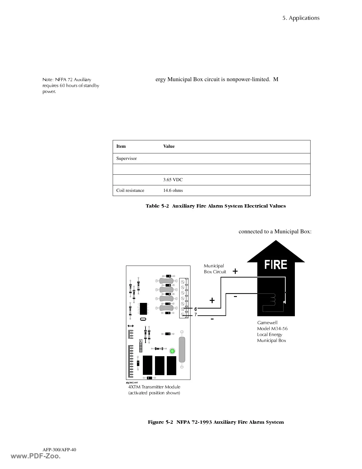
Figure 5-2 shows a typical wiring diagram of 4XTM connected to a Municipal Box:
)LJXUH 1)3$ $X[LOLDU\ )LUH $ODUP 6\VWHP
Item Value
Supervisory current 5.0 mA
Trip current 0.35 A (subtracted from notification appliance power)
Coil voltage 3.65 VDC
Coil resistance 14.6 ohms
0XQLFLSDO
%R[ &LUFXLW
*DPHZHOO
0RGHO 0
/RFDO (QHUJ\
0XQLFLSDO %R[
;70 7UDQVPLWWHU 0RGXOH
DFWLYDWHG SRVLWLRQ VKRZQ
www.PDF-Zoo.com

 Loading...


