Field-Wiring the Modules
,QVWDOODWLRQ
AFP-300/AFP-400 Installation PN 50253:C1 05/22/97 2-25
)LHOG:LULQJWKH0RGXOHV
This section contains instructions for the following:
• Notification Appliance Circuit (NAC) Wiring
• Field-wiring a ICM-4 and an ICE-4 (NFPA Style Y and Z)
• Field-wiring a CRM-4 and the CRE-4
• Field-wiring the MPS-400 Power Supply
• Field-wiring an ARM-4
1RWLILFDWLRQ $
OLDQFH&LUFXLW1$& : LULQ
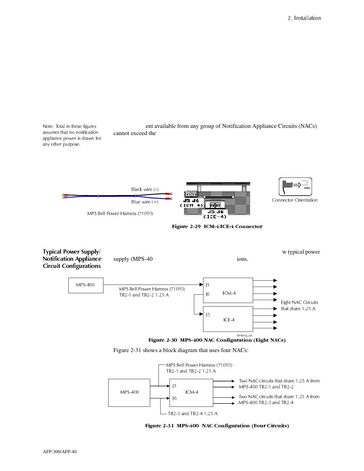
1RWH 7RWDO LQ WKHVH ILJXUHV
DVVXPHV WKDW QR QRWLILFDWLRQ
DSSOLDQFH SRZHU LV GUDZQ IRU
DQ\ RWKHU SXUSRVH
The total current available from any group of Notification Appliance Circuits (NACs)
cannot exceed the following:
• 3.0 A when powered from the AVPS-24; or
• 1.25 A when powered from an MPS-400 output.
Figure 2-29 shows the bottom wire connections of the ICM-4 and the ICE-4 modules:
)LJXUH ,&0,&( &RQQHFWRU
036,&01$&&RQIL
XUDWLRQV
7\SLFDO 3RZHU 6XSSO\
1RWLILFDWLRQ $SSOLDQFH
&LUFXLW &RQILJXUDWLRQV
Figure 2-30, Figure 2-31, Figure 2-32, Figure 2-33, and Figure 2-34 show typical power
supply (MPS-400 and AVPS-24) to NAC configurations.
)LJXUH 036 1$& &RQILJXUDWLRQ (LJKW 1$&V
Figure 2-31 shows a block diagram that uses four NACs:
)LJXUH 036 1$& &RQILJXUDWLRQ )RXU &LUFXLWV
036 %HOO 3RZHU +DUQHVV
%ODFN ZLUH ²
&RQQHFWRU 2ULHQWDWLRQ
%OXH ZLUH
036
(LJKW 1$& &LUFXLWV
WKDW VKDUH $
,&(
,&0
-
-
-
036 %HOO 3RZHU +DUQHVV
7% DQG 7% $
036 %HOO 3RZHU +DUQHVV
7% DQG 7% $
7ZR 1$& FLUFXLWV WKDW VKDUH $ IURP
036 7% DQG 7%
7ZR 1$& FLUFXLWV WKDW VKDUH $ IURP
036 7% DQG 7%
7% DQG 7% $
036
-
-
,&0
www.PDF-Zoo.com

 Loading...


