Installing an Auxiliary Relay Module (ARM-4)
,QVWDOODWLRQ
AFP-300/AFP-400 Installation PN 50253:C1 05/22/97 2-11
,QVWDOOLQJDQ$X[LOLDU\5HOD\0RGXOH$50
2YHUYLHZ
The ARM-4 module can be driven by a CRM-4 or a CRE-4. Each ARM-4 can support
one CRM-4 or one CRE-4. If using auxiliary relays for both modules, mount two
ARM-4s in separate positions.
1RWH )RU HDVH RI LQVWDOODWLRQ
DQG VHUYLFH PRXQW WKH $50
PRGXOH LQ D GHGLFDWHG SRVLWLRQ
RQ WKH FKDVVLV LI DYDLODEOH ZLWK
QR PRGXOH RU H[SDQGHU ERDUG
DERYH LW 7KH $50 FDQ DOVR
PRXQW LQ WKH XSSHU ULJKW FRUQHU
RI WKH &$%$$
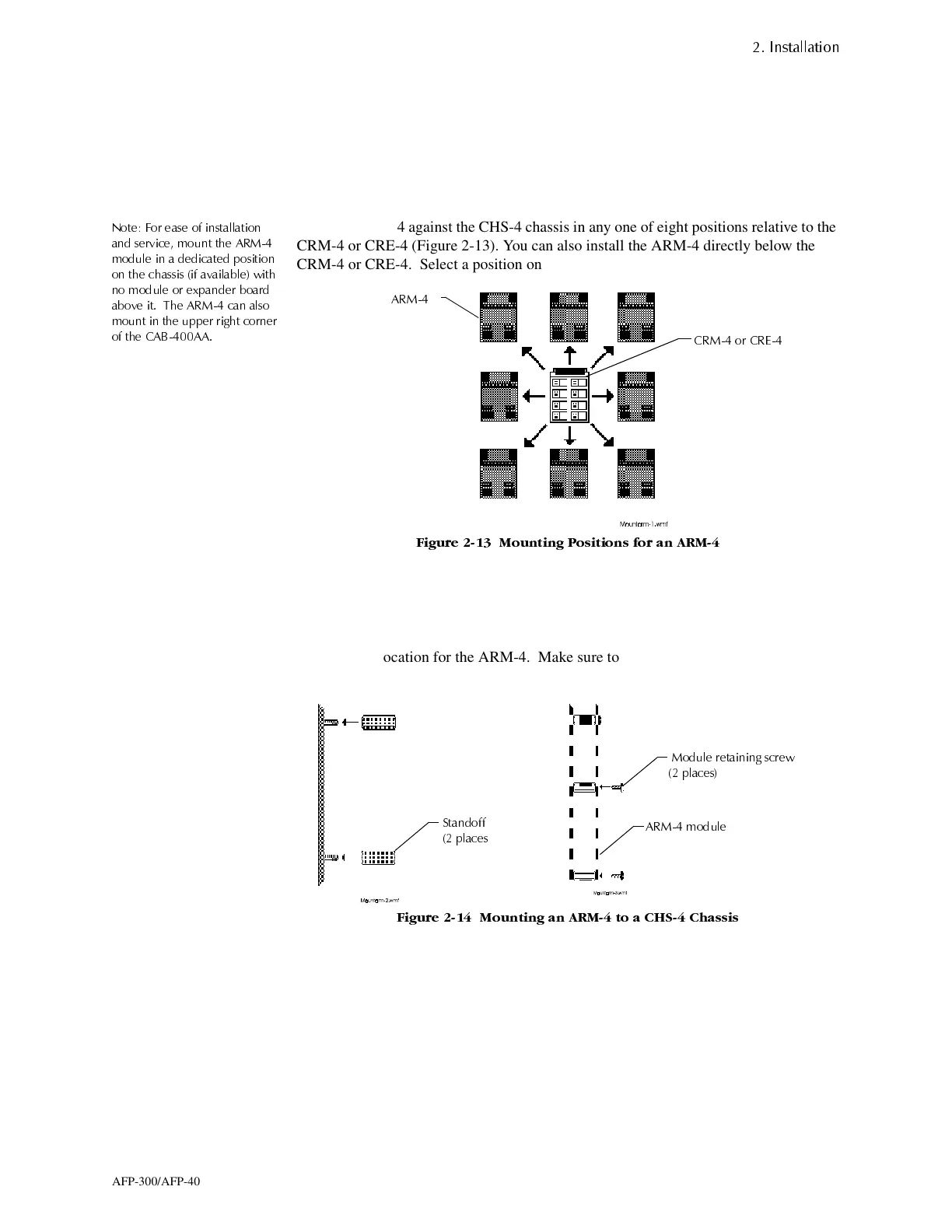
Place the ARM-4 against the CHS-4 chassis in any one of eight positions relative to the
CRM-4 or CRE-4 (Figure 2-13). You can also install the ARM-4 directly below the
CRM-4 or CRE-4. Select a position on the CHS-4 chassis for the ARM-4:
)LJXUH 0RXQWLQJ 3RVLWLRQV IRU DQ $50
0RXQWLQ
WKH$500RGXOHWRD&+6&KDVVLV
1. Select a mounting position for the ARM-4 module on the CHS-4 chassis.
2. Secure the two loose standoffs to the screw mounts on the CHS-4 chassis at the
selected location for the ARM-4. Make sure to install existing standoffs in the
locations shown in Figure 2-14:
)LJXUH 0RXQWLQJ DQ $50 WR D &+6 &KDVVLV
3. Position the ARM-4 module over the existing standoffs on the chassis; then, fasten
the ARM-4 module to the chassis with the two module retaining screws as shown
in Figure 2-14.
$50
&50 RU &5(
6WDQGRII
SODFHV
0RGXOH UHWDLQLQJ VFUHZ
SODFHV
$50 PRGXOH
www.PDF-Zoo.com

 Loading...


