,QVWDOODWLRQ
Connecting the MPS-400 Power Cables
2-14 AFP-300/AFP-400 Installation PN 50253:C1 05/22/97
&RQQHFWLQJ )RXU:LUH
6PRNH 'HWHFWRU 9'&
3RZHU 036 7%
MPS-400 TB2 terminals TB2-5 (+) and TB2-6 (–) provide up to 1.25 A of current for
four-wire smoke detectors. A system reset removes the 24 VDC power from MPS-400
TB2. 24 VDC low-noise four-wire smoke detector power is power-limited but must be
supervised. To provide supervision, install an end-of-line listed power supervision
relay. Connect the power supervision relay in series with an Initiating Device Circuit
(IDC). The four-wire power circuit energizes the power supervision relay.
1RWLILFDWLRQ $SSOLDQFH
3RZHU 9'&
TB2 terminals TB2-1 (+) and TB2-2 (–) provide up to 1.25 A of nonresettable low-
noise current for powering notification appliances. TB2 terminals TB2-3 (+) and
TB2-4 (–) also provide 1.25 A of nonresettable low-noise current. TB2 terminals
TB2-5 (+) and TB2-6 (–) provide 1.25 A of resettable power.
$QQXQFLDWRU 3RZHU
9'&
Power ACS annunciators from the four-wire smoke detector outputs, or from one of the
NAC power outputs. All outputs provide the filtered, low-noise, power-limited source
required by the annunciators. The power run to the annunciators is supervised by the
annunciator (for a Loss of Communications error). Annunciator wiring must run
separate from NAC wiring. You can use any of the NAC outputs, but do not connect an
NAC to the output selected for powering the annunciators.
6\VWHP +DUQHVV
&RQQHFWLRQV
Make system connections as follows as shown in Table 2-7:
Table 2-7 System Harness Connections
6\VWHP 3RZHU
&RQQHFWLRQV
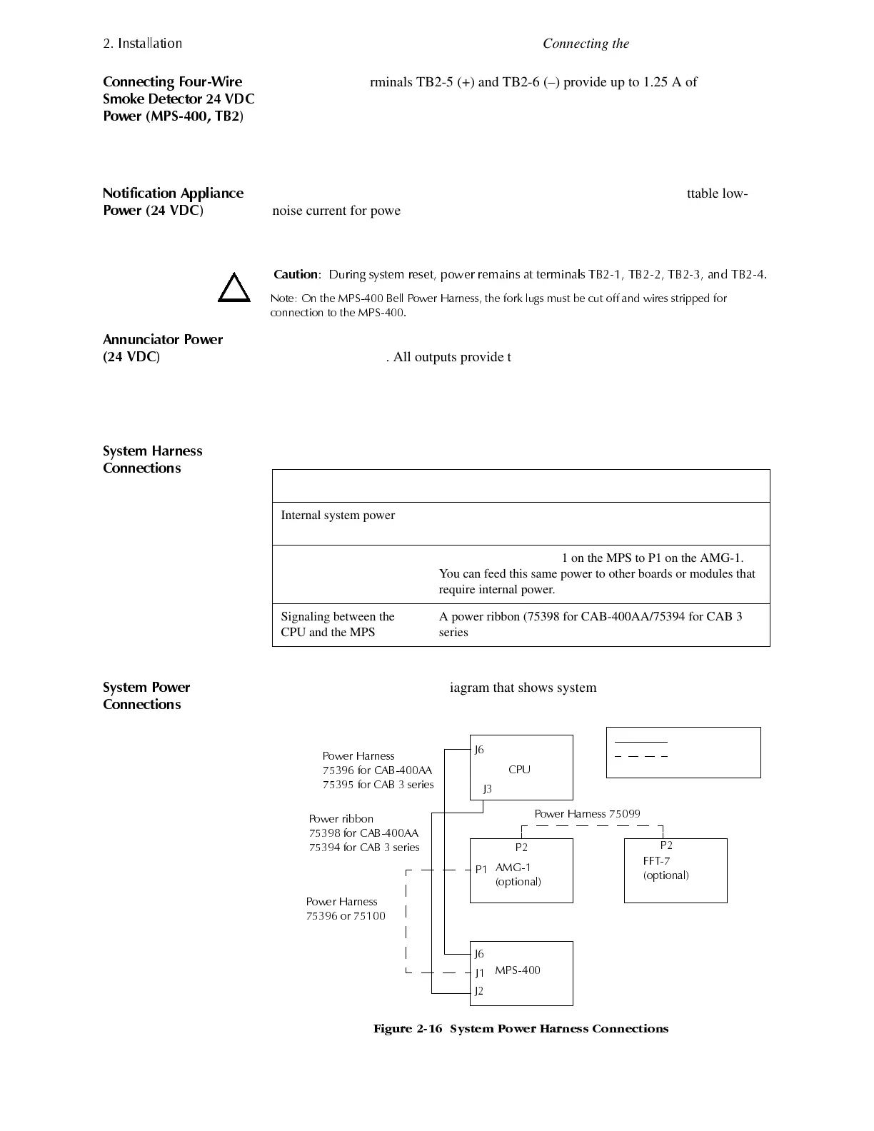
Figure 2-16 contains a block diagram that shows system power connections between
the MPS-400 and AFP-300/AFP-400 system components:
)LJXUH 6\VWHP 3RZHU +DUQHVV &RQQHFWLRQV
&DXWLRQ
'XULQJ V\VWHP UHVHW SRZHU UHPDLQV DW WHUPLQDOV 7% 7% 7% DQG 7%
1RWH 2Q WKH 036 %HOO 3RZHU +DUQHVV WKH IRUN OXJV PXVW EH FXW RII DQG ZLUHV VWULSSHG IRU
FRQQHFWLRQ WR WKH 036
For... Connect...
Internal system power The power harness (75396 for CAB-400AA/75395 for CAB 3
series) from J6 on the MPS to J6 on the CPU.
AMG-1 power A power harness from J1 on the MPS to P1 on the AMG-1.
You can feed this same power to other boards or modules that
require internal power.
Signaling between the
CPU and the MPS
A power ribbon (75398 for CAB-400AA/75394 for CAB 3
series) to J2 on the MPS.
&38
$0*
RSWLRQDO
036
))7
RSWLRQDO
Standard
Optional
3RZHU +DUQHVV
IRU &$%$$
IRU &$% VHULHV
3RZHU ULEERQ
IRU &$%$$
IRU &$% VHULHV
3RZHU +DUQHVV
RU
3RZHU +DUQHVV
-
-
3
3
-
-
-
3
www.PDF-Zoo.com

 Loading...


