Specifications
6\VWHP 2YHUYLHZ
AFP-300/AFP-400 Installation PN 50253:C1 05/22/97 1-7
3RZHU2XWSXWV
1RWH 7KH 036 SURYLGHV D
WRWDO RI $ RI SRZHU VKDUH G
E\ DOO LQWHUQDO PRGXOHV DQG
HDFK 036 FLUFXLW )RU
SRZHU UHTXLUHPHQWV UHIHU WR
WKH SRZHU VXSSO\ FDOFXODWLRQ
WDEOHV LQ $SSHQGL[ *
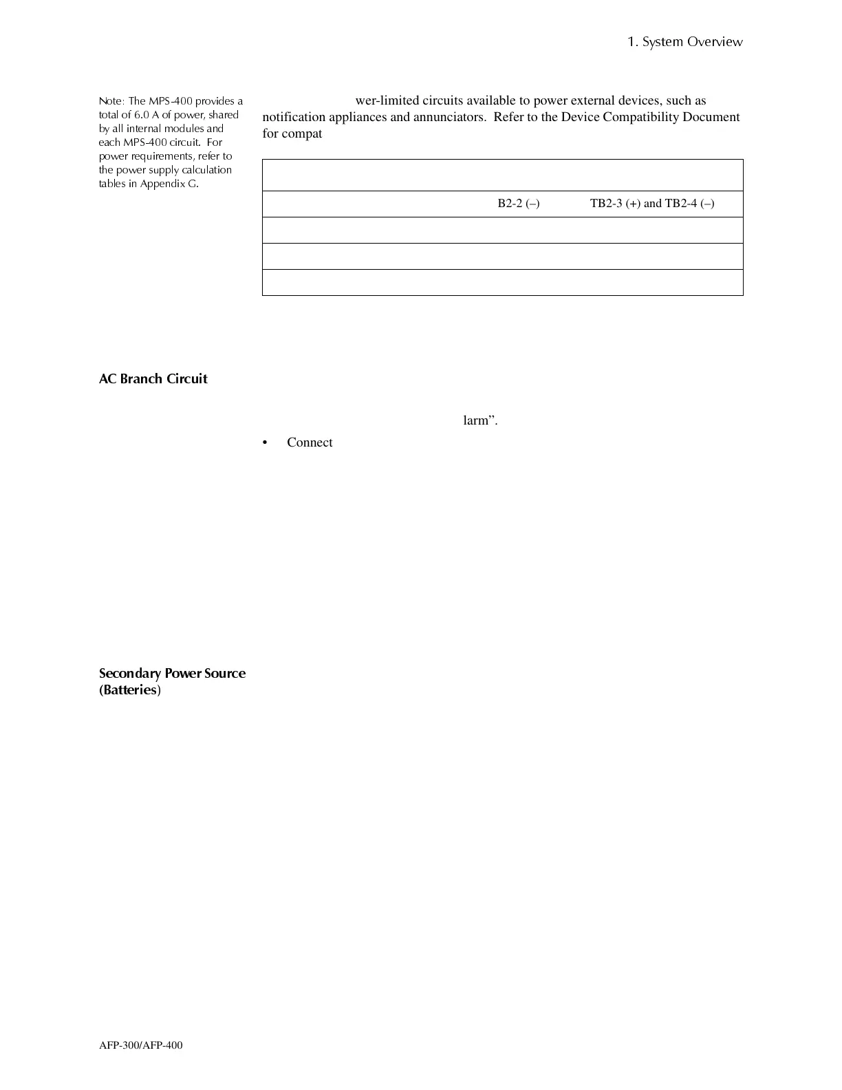
There are two power-limited circuits available to power external devices, such as
notification appliances and annunciators. Refer to the Device Compatibility Document
for compatible devices and notification appliances.
Table 1-6 Power-Limited Circuits
2SHUDWLQJ3RZHU
$& %UDQFK &LUFXLW
This control panel requires connection to a separate dedicated AC branch circuit.
Follow these guidelines when connecting the AC branch circuit:
• Label the branch circuit “Fire Alarm”.
• Connect the branch circuit to the line side of the main power feed of the protected
premises.
• Do not power other equipment from the fire alarm branch circuit.
• Run the branch circuit wire continuously, without any disconnect devices, from the
power source to the fire alarm control panel.
• Overcurrent protection for this circuit must comply with Article 760 of the
National Electrical Codes, as well as local codes.
• Use 14 AWG wire with 600 VAC insulation for this branch circuit.
Connect the earth ground terminal (MPS-400, TB1-3) to a solid earth ground (a metallic,
cold water pipe may be suitable in some installations). This connection is vital to
maintaining the control panel's immunity to unwanted transients generated by lightning
and electrostatic discharge.
6HFRQGDU\ 3RZHU 6RXUFH
%DWWHULHV
The battery charger is current-limited and can recharge sealed lead-acid type batteries.
The charger shuts off when the control panel is in alarm.
Item Circuit A Circuit B
Terminals TB2-1 (+) and TB2-2 (–) TB2-3 (+) and TB2-4 (–)
Nominal Voltage 24 VDC 24 VDC
Max rated current 1.25 A DC 1.25 A DC
Max ripple voltage 100 mVrms 100 mVrms
www.PDF-Zoo.com

 Loading...


