Connecting the MPS-400 Power Cables
,QVWDOODWLRQ
AFP-300/AFP-400 Installation PN 50253:C1 05/22/97 2-13
&RQQHFWLQJWKH0363RZHU&DEOHV
036(OHFWULFDO&RQQHFWLRQV
MPS-400 electrical connections include the following:
• Primary AC power source – 120 VAC, 50/60 Hz, 3.0 A or 240 VAC, 50/60 Hz,
1.5 A from line voltage source.
• Secondary power source – 24 VDC from batteries, installed in the control panel (or
in an optional battery cabinet), provides backup power if the system loses primary
power. Secondary (battery) power is required to support the system during loss of
primary power.
:DUQLQJ
5HPRYH DOO SRZHU VRXUFHV WR HTXLSPHQW ZKLOH FRQQHFWLQJ HOHFWULFDO FRPSRQHQWV
/HDYH WKH PDLQ SRZHU EUHDNHU RII XQWLO LQVWDOODWLRQ RI WKH HQWLUH V\VWHP LV FRPSOHWH
0DNH VXUH WR VHW WKH 9ROWDJH 6HOHFWLRQ 6ZLWFK 6 WR WKH FRUUHFW YROWDJH
&RQQHFWLQ
WKH036WR$&3RZHU7%
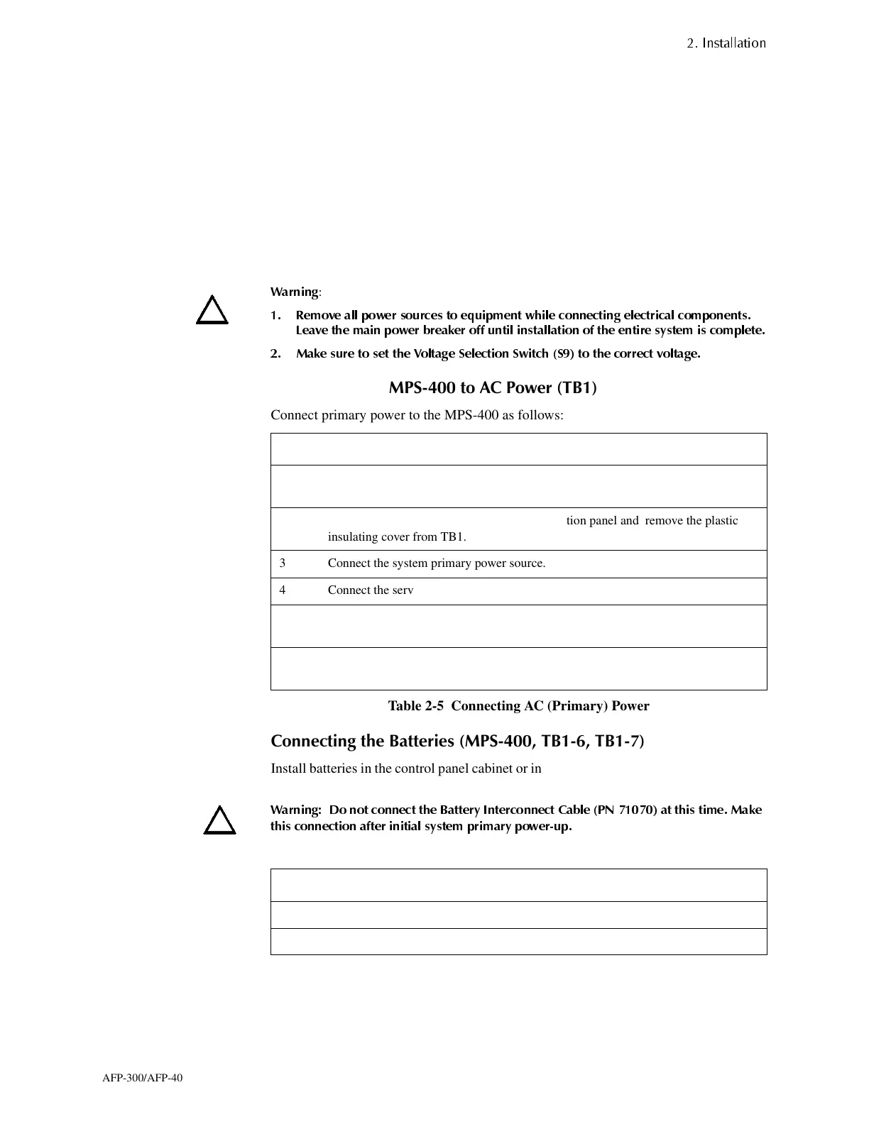
Connect primary power to the MPS-400 as follows:
Table 2-5 Connecting AC (Primary) Power
&RQQHFWLQ
WKH%DWWHULHV0367%7%
Install batteries in the control panel cabinet or in a separate battery cabinet which can be
mounted up to 20 feet away from the control panel.
:DUQLQJ 'R QRW FRQQHFW WKH %DWWHU\ ,QWHUFRQQHFW &DEOH 31 DW WKLV WLPH 0DNH
WKLV FRQQHFWLRQ DIWHU LQLWLDO V\VWHP SULPDU\ SRZHUXS
Connect the battery as follows:
Table 2-6 Connecting Batteries
Step Action
1 Set the Voltage Select Switch (S9 on the MPS-400) to match the incoming AC line
voltage (120 VAC or 230 VAC).
2 Turn off the breaker at the main power distribution panel and remove the plastic
insulating cover from TB1.
3 Connect the system primary power source.
4 Connect the service ground to TB1-3 (labeled EARTH).
5 Connect the primary Neutral line to TB1-2 and the primary Hot line to TB1-4
(marked HOT).
6 When finished making connections, reinstall the plastic insulating cover over TB1
(Switch S9 on the MPS-400).
Step Action
1 Connect the battery positive terminal to TB1 terminal 6 (+).
2 Connect the battery negative terminal to TB1 terminal 7 (–).
www.PDF-Zoo.com

 Loading...


