2 Installing Ethernet Networks
2-10
CJ-series EtherNet/IP Units Operation Manual for NJ-series CPU Unit (W495)
2-5 Connecting to the Network
The following standards and specifications apply to the connectors for the Ethernet twisted-pair cable.
• Electrical specifications: Conforming to IEEE 802.3 standards.
• Connector structure: RJ45 8-pin Modular Connector (conforming to ISO 8877)
Precautions for Correct UsePrecautions for Correct Use
• Turn OFF the power supply to the Controller before you connect or disconnect twisted-pair
cable.
• Allow more than enough space for the bending radius of the twisted-pair cable. The space that
is required depends on the communications cable and connector that you use. Contact the
manufacturer or sales agent.
1 Lay the twisted-pair cable.
2 Connect the cable to the Ethernet switch.
3 Connect the twisted-pair cable to the connector on the EtherNet/IP Unit. Be sure to press the connec-
tors (both the Ethernet switch side and Ethernet side) until they lock into place.
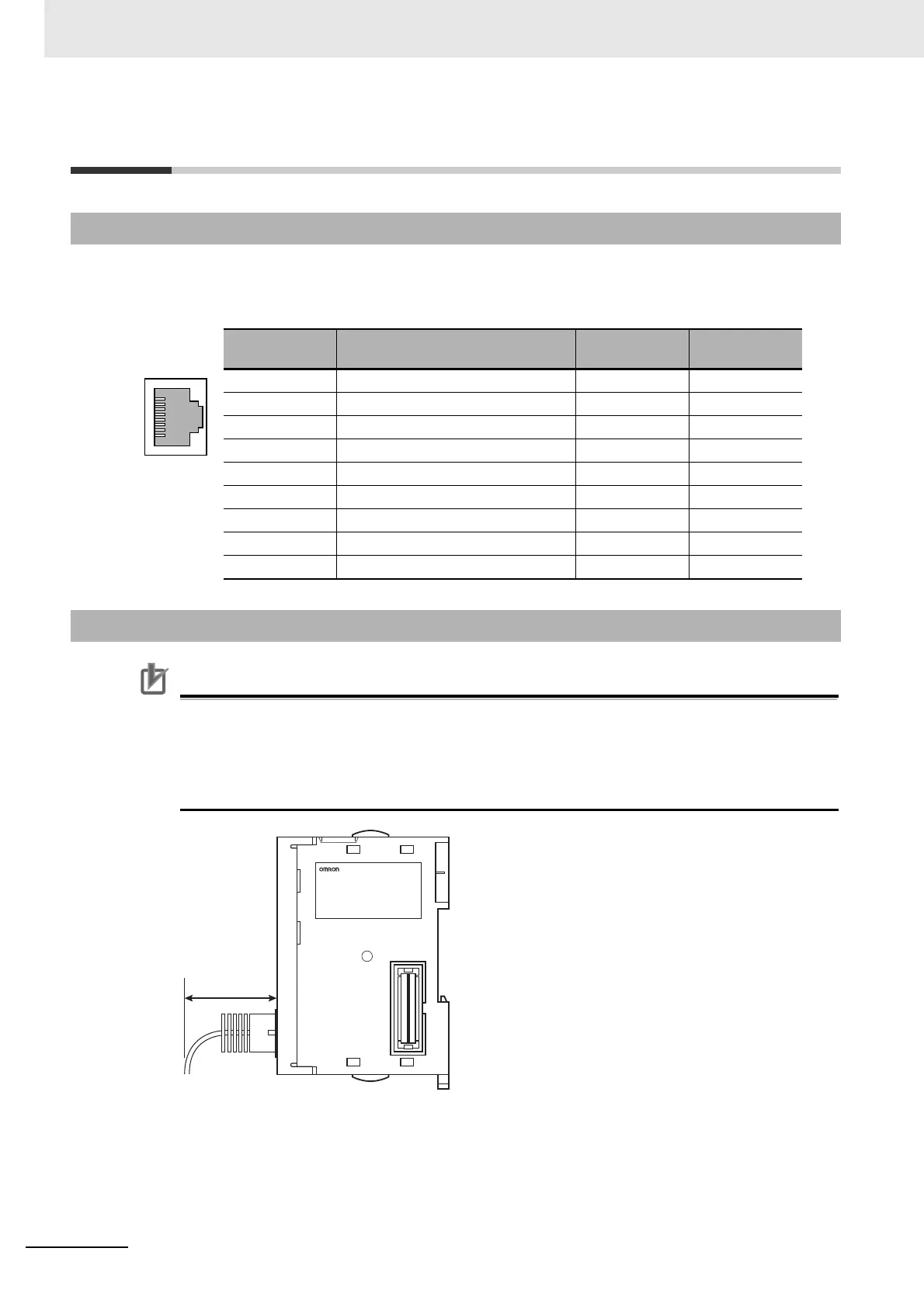
2-5-1 Ethernet Connectors
Connector pin Signal name Abbr.
Signal direc-
tion
1 Transmission data + TD+ Output
2 Transmission data – TD− Output
3 Reception data + RD+ Input
4 Not used. --- ---
5 Not used. --- ---
6 Reception data – RD− Input
7 Not used. --- ---
8 Not used. --- ---
Hood Frame ground FG ---
2-5-2 Connecting the Cable

 Loading...
