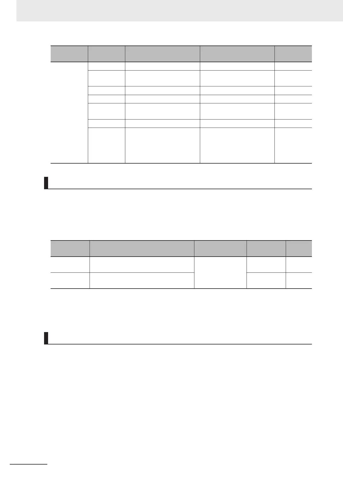
Parameter
No.
Data Function name Reference item
Reference
page
Output Termi-
nal [DO1]
Function Se-
lection (E20),
Output Termi-
nal [DO2]
Function Se-
lection (E21)
Output Termi-
nal [ROA,
ROB] Func-
tion Selection
(E27)
0 RUN (Signal during run)
Signal during run page 5-68
1
FA1 (Constant speed arrival
signal)
Constant speed arrival signal page 5-70
99 AL (Alarm signal) Alarm signal page 5-71
70 ZS (0 Hz detection signal) 0 Hz detection signal page 5-71
10
IRDY (Operation ready com-
pletion)
Operation ready completion page 5-68
52 FWR (Forward run signal) Forward run signal page 5-69
53 RVR (Reverse run signal) Reverse run signal page 5-69
Operation Ready Completion Signal (IRDY)
• This signal is output when the inverter becomes ready to operate (ready to accept the RUN com-
mand).
• To output this signal, allocate “10: IRDY (Operation ready)” to Output Terminal [DO1] Function Se-
lection (E20), Output T
erminal [DO2] Function Selection (E21) or Output Terminal [ROA, ROB]
Function Selection (E27).
Parameter
No.
Function name Data Default data Unit
E20, E21
Output Terminal [DO1] Function Selection,
Output Terminal [DO2] Function Selection
10: IRDY (Operation
ready completion)
- -
E27
Output Terminal [ROA, ROB] Function Se-
lection
99 -
• When this signal is not output, the inverter does not operate even if the RUN command is input.
• If this signal is not output, check if the input power supply voltage (L1/R, L2/S,L3/T) is within the
specification range.
Signal during RUN (RUN), Inverter Output Signal (RUN2)
• This signal is output while the inverter is running (RUN command ON).
• The signal during RUN (RUN) and inverter output signal (RUN2) are output also when the inverter is
decelerating after the RUN command turns OFF.
•
When in a free-run state (output shutoff status), the signal during RUN (RUN) and inverter output
signal (RUN2) are not output even if the RUN command is turned ON. (Note that on the Operator,
the RUN LED is lit when the RUN command is ON.)
• The signal during RUN (RUN) is not output while DC braking is operating, during tuning of motor
parameters while stopped, and during pre-excitation by the EXITE terminal. The inverter output sig-
nal (RUN2) is output.
• To output this signal, allocate “00: RUN” and “35: RUN2” to Output Terminal [DO1] Function Selec-
tion (E20), Output Terminal [DO2] Function Selection (E21) or Output Terminal [ROA, ROB] Func-
tion Selection (E27).
5 Basic Settings
5-68
M1 Series Standard Type User's Manual (I669)
 Loading...


