Positional deviation is closely related to positioning frequency and position command gain. When a
certain frequency reference is output at a certain position reference gain, a constant positional devia-
tion is always required. Due to this fact, positional deviation can be improved by either increasing the
detection level of excessive positioning deviation (d223, d224) or by increasing the position control
gain (d203 and d204) when the excessive positional deviation alarm (d0) occurs.
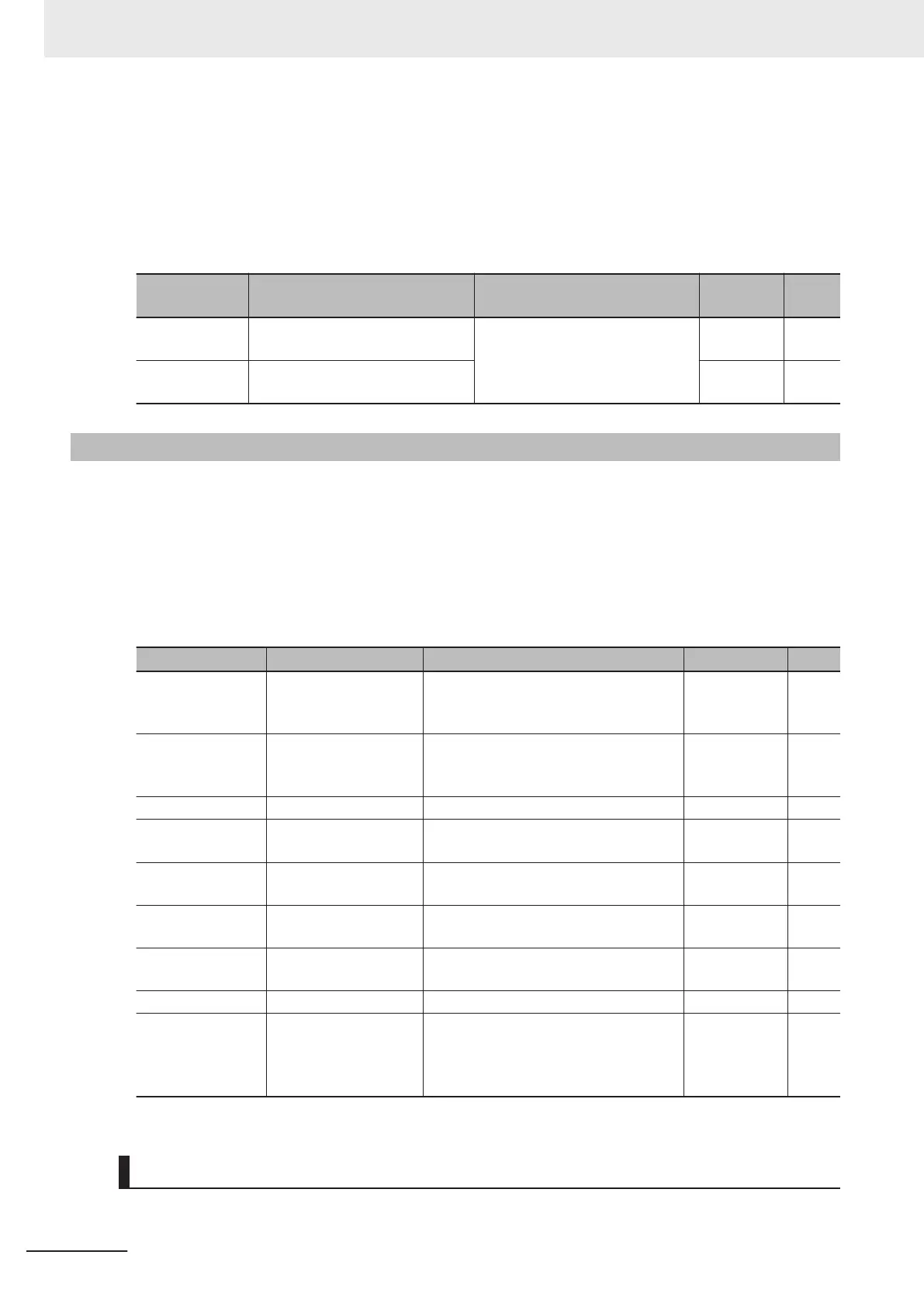
Parameter No. Function name Data
Default
data
Unit
d223
Detection Level of Excessive Po-
sitioning Deviation (MSB)
0: Disable (MSB: 0, LSB: 0)
1 to 268435455 (MSB: 0 to 4,095,
LSB: 0 to 65,535)
0 -
d224
Detection Level of Excessive Po-
sitioning Deviation (LSB)
0 -
6-7-18
Touch Probe (Latch) Function
This is a function that latches the feedback position and the time stamp, when the external latch input
signal or the encoder Z-phase is started.
This function is disabled if neither of “187: EXT1 (External latch input 1)” and “188: EXT2 (External
latch input 2)” is allocated to Input Terminal [DI1] Function Selection (E01) and Input Terminal [DI2]
Function Selection (E02), and if the selection trigger is not encoder Z-phase.
This function is also disabled when bit 0 (Latch function 1) and bit 8 (Latch function 2) of Touch Probe
Function (H437) are 0.
Parameter No. Function name Data Default data Unit
H435
Touch Probe 1 Source 1: External Latch Input 1 (EXT1)
2: External Latch Input 2 (EXT2)
6: Encoder Phase Z
1 -
H436
Touch Probe 2 Source 1: External Latch Input 1 (EXT1)
2: External Latch Input 2 (EXT2)
6: Encoder Phase Z
1 -
H437 Touch Probe Function 0000 to FFFF hex 0 -
W148
Touch Probe 1 Positive
Edge (MSB)
-4096 to 4095
0 -
W149
Touch Probe 1 Positive
Edge (LSB)
0 to 65535
0 -
W150
Touch Probe 2 Positive
Edge (MSB)
-4096 to 4095
0 -
W151
Touch Probe 2 Positive
Edge (LSB)
0 to 65535
0 -
W152 Touch Probe Status 0000 to FFFF hex 0 -
E01,E02
Input Terminal [DI1]
Function Selection, In-
put T
erminal [DI2]
Function Selection
187: EXT1 (External latch input 1)
*1
188: EXT2 (External latch input 2)
*1
- -
*1. External latch cannot be allocated to other than multifunction input DI1 and DI2.
Setting the Trigger Signal
The trigger of the touch probe function can be selected as shown in the figure below.
6 Vector Control and Applied Functions
6-62
M1 Series Standard Type User's Manual (I669)
 Loading...


