Bit Symbol Description
6 TL Torque limiting
5 NUV Main Circuit DC Voltage > Undervoltage level
4 BRK During braking
3 INT Inverter output is being intercepted
2 EXT During DC braking
1 REV During reverse rotation
0 FWD During forward rotation
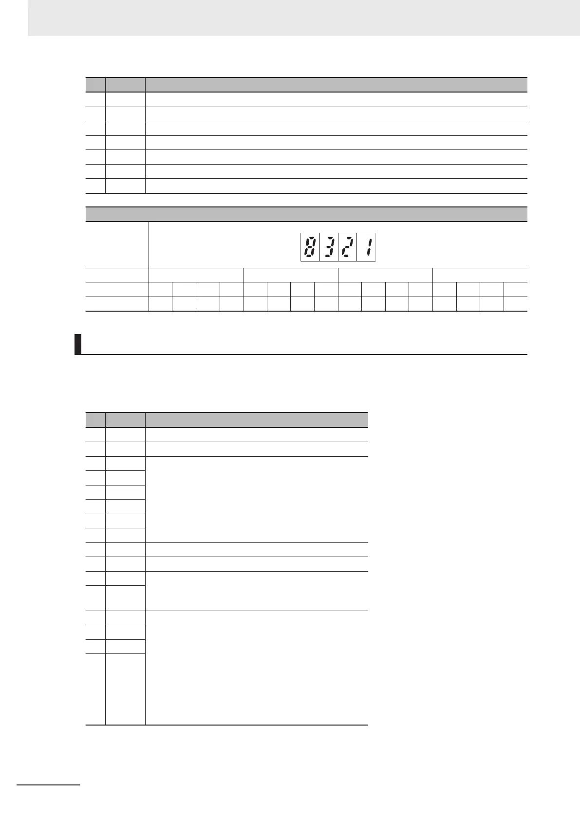
Display example of operation status
Hexadecimal
LED monitor
LED No. LED4 LED3 LED2 LED1
Bit 15 14 13 12 11 10 9 8 7 6 5 4 3 2 1 0
Binary 1 0 0 0 0 0 1 1 0 0 1 0 0 0 0 1
Running Status 2 Monitor [3_23]
The operation status 2 displays the status allocated to each bit by a four-digit hexadecimal.
The allocation for 0 to 15 bits of the operation status is described in the table below.
The display of operation status 2 is the same as that of “3_07: Operation status” monitor.
Bit Symbol Description
15 - Synchronous motor drive
14 - During EN circuit diagnosis
13 -
Not used
12 -
11 -
10 -
9 -
8 -
7 - 1, during speed limitation (torque control)
6 - Not used
5 - Motor selection
00: 1st motor
01: 2nd motor
4 -
3 - Control Method
0000: V/f control without slip compensation
0001: Dynamic torque vector control
0010: V/f control with slip compensation
001
1: V/f control with speed sensor
0100: Dynamic torque vector control with speed sensor
0101: Vector control without speed sensor
01
10: Vector control with speed sensor
1011: Torque control (Vector control with speed sensor)
2 -
1 -
0 -
7 Other Functions
7-10
M1 Series Standard Type User's Manual (I669)
 Loading...


