7-1-2
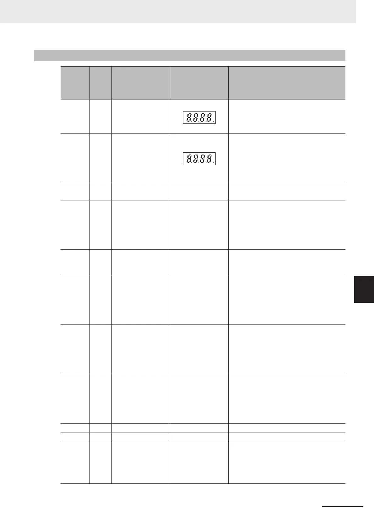
I/O check
Item No.
Pa-
rame-
ter
No.
Item Range
Display contents (The value range de-
pends on the model)
4_00
W40,
W41
Input Terminal Moni-
tor, Output Signal
Monitor
Displays the ON/OFF status of the input ter-
minals [DI1] to [DI7], output terminals [DO1],
[D12], [ROA, ROB] and the [EN1] and [EN2]
terminals.
4_01
W42,
W43
Communications In-
put Signal Monitor
,
Communications
Control Output Sig-
nal Monitor
Displays the ON/OFF status of the input ter-
minals [DI1] to [DI7], [EN1], [EN2], RST (re-
set command), REV (reverse command),
FWD (forward command) and the output ter-
minals [DO1], [DO2], [ROA, ROB] instructed
via communication based on RS-485.
4_02 W44
Input Terminal [AI1]
Input Voltage
0.0 to 12.0 [V]
The input voltage of the analog input termi-
nal [AI1] is displayed in increments of 0.1 V.
4_03 W45
Input T
erminal
[AI2]AII Input Cur-
rent (AII)
0.0 to 30.0 [mA]
The input current of the analog input termi-
nal [AI2] (All) is displayed in increments of
0.1 mA.
*Since this item is shared with other terminal
functions, “0.0” is displayed when it is disa-
bled due to switching by the hardware SW.
4_04 W46
Output T
erminal
[AO]AOV Output
Voltage
0.0 to 12.0 [V]
The output voltage of analog output terminal
[AO] (AOV) is displayed in increments of 0.1
V.
4_06 W48
Output T
erminal
[AO]PO Output Fre-
quency
0 to 9999 [p/s]
1000 to 3200 [10p/s]
The number of output pulses per unit time of
analog output terminal [AO] (PO) is dis-
played in (p/s).
If the monitor value is 10000 or above, the
x10 LED lights up and the value of “monitor
value/10" is displayed.
4_07 W49
Input Terminal [AI2]
Input Voltage (AIV)
0.0 to 12.0 [V]
The input voltage of analog input terminal
[AI2] (AIV) is displayed in increments of 0.1
V.
*Since this item is shared with other terminal
functions, “0.0” is displayed when it is disa-
bled due to switching by the hardware SW.
4_08
W50
Terminal [AO](AOI)
output current
0.0 to 30.0 [mA]
The output current of analog output terminal
[AO] (AOI) is displayed in increments of 0.1
mA.
*Since this item is shared with other terminal
functions, “999” is displayed when it is disa-
bled due to switching by the hardware SW.
4_15 W53
Reserved - -
4_16 W54 Reserved - -
4_17 W55
Pulse Input (A/B
Phase [PIA][PIB])
-327 to -99.9 to -9.99
to 99.99 to 327.6
[kp/s]
The pulse rate entered in the pulse input ter-
minal [PIA] [PIB] is displayed. (in increments
of 0.01 [kp/s])
Displayed without quad edge evaluation re-
gardless of the pulse format.
7 Other Functions
7-11
M1 Series Standard Type User's Manual (I669)
7-1 Status Monitors
7
7-1-2 I/O check
 Loading...


