7-3-5
Analog Output Function Selection
On this inverter, current output, voltage output and pulse output can be selected.
Analog output terminal [AO] can be switched between voltage output (AOV) (factory default setting),
current output (AOI) and pulse output (PO) according to the setting of analog output selector switch
(SW5).
Analog output terminal [AO] (AOV) 0 to 10V
Analog output terminal [AO] (AOI) 4 to 20 mA, 0 to 20 mA
Analog output terminal [AO] (PO) Pulse output
• For details on analog output adjustment, refer to 7-3-6
Analog Output Adjustment Function on page
7-48.
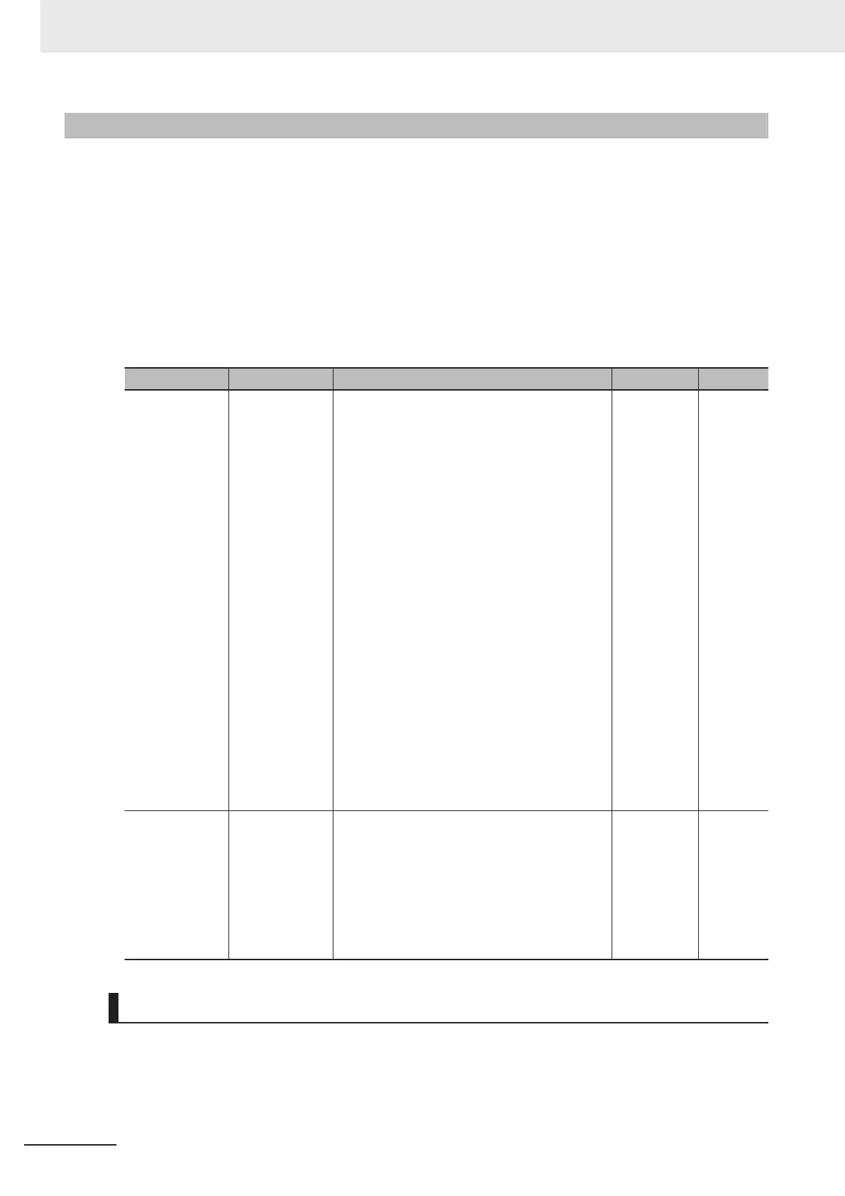
Parameter No. Function name Data Default data Unit
F31
Output Terminal
[AO] Function
Selection
0: Output frequency1 (before slip compensa-
tion)
1: Output frequency2 (after slip compensation)
2: Output current
3: Output voltage
4: Output torque
5: Load ratio
6: Power consumption
7: PID feedback
8: Actual/Estimated speed
9: Main circuit DC voltage
10: Communication data AO
13: Motor output
14: Calibration (+)
15: PID command (SV)
16: PID output (MV)
17: Position error in master-follower operation
(Bipolar)
18: Heatsink temperature
21: PG feedback value
27: Thermal load rate
28: Internal Acc/Dec frequency
29: Output torque (Bipolar)
0 -
F29
Output Terminal
[AO] Mode Se-
lection
0: Output in voltage (0 to 10 VDC)
(SW5 = AOV setting)
1: Output in current (4 to 20mADC)
(SW5 = AOI setting)
2: Output in current (0 to 20mADC)
(SW5 = AOI setting)
3: Pulse output
(SW5 = PO setting)
0 -
Scaling of Analog Output Signal
The relationship between analog output signals and digital values for each individual analog output
range is as follows.
7 Other Functions
7-46
M1 Series Standard Type User's Manual (I669)
 Loading...


