+200-2
00 +100-100
100% 0%
+180-180 +90-90
100
50
25
0
0
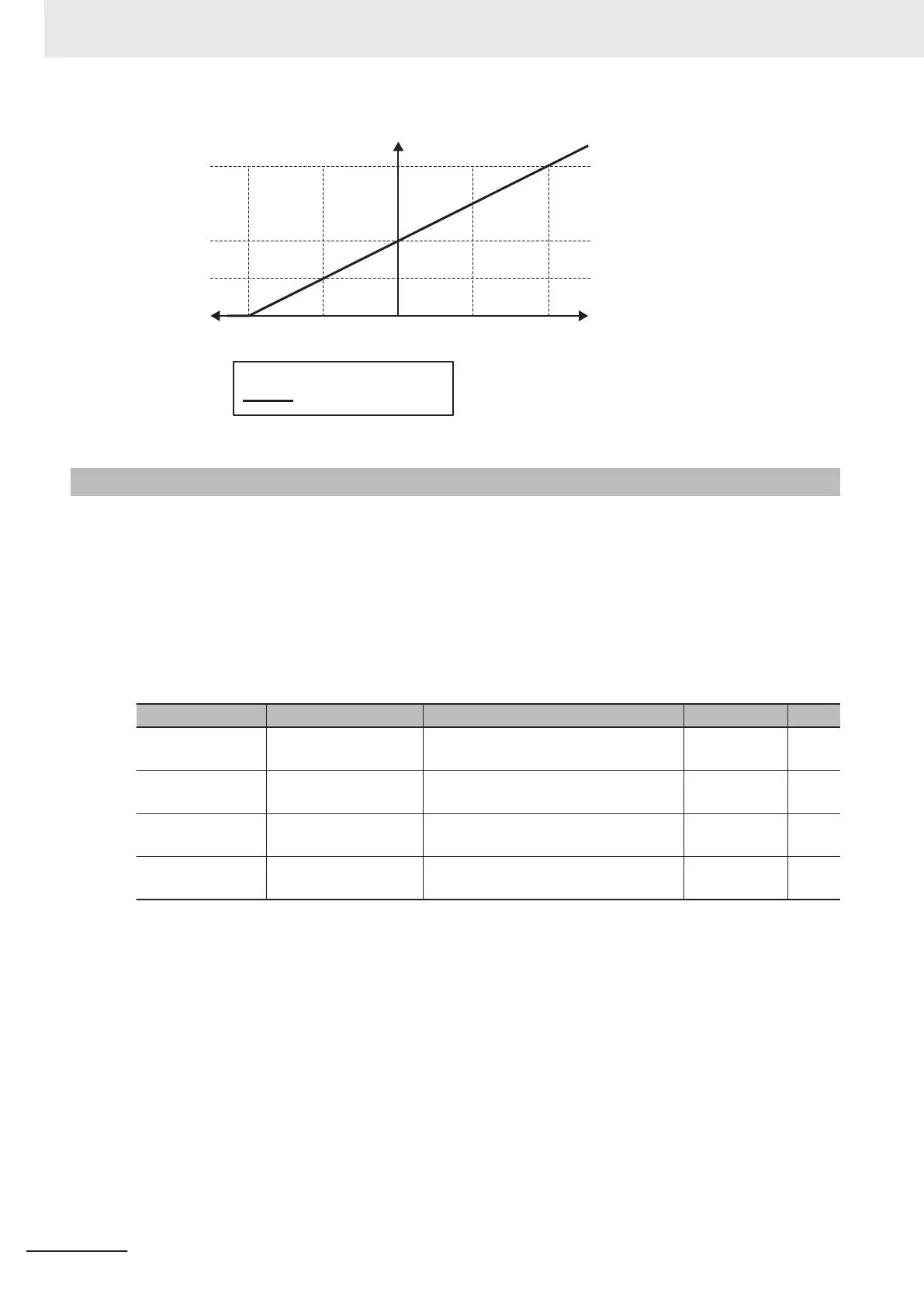
Analog output [%]
Torque value [%]
Master follower position error [deg]
Output Terminal
[AO] Gain (F30)
Output Terminal
[AO] Bias (F59)
7-3-6
Analog Output Adjustment Function
This function adjusts the bias and gain of the analog output terminal [AO]. It is also used for setting the
filter and pulse rate.
•
In the voltage (AOV)/current (AOI)/pulse (PO) outputs, a filter can be applied to monitor data select-
ed for output. Increasing the set value results in a slow response. This is the filter time constant for a
sett value of 0.00 to 5.00 (s).
• In the pulse (PO) output, set the number of pulses when the set monitor output becomes 100% in
accordance with the specifications of the counter to be connected, etc.
Parameter No. Function name Data Default data Unit
F30
Output Terminal [AO]
Gain
0 to 300% 100. %
F59
Output Terminal [AO]
Bias
-100.0% to 100% 0.0 %
F58
Output Terminal [AO]
Filter
0.00 to 5.00 s 0.00 s
F33
Output Terminal [AO]
Pulse Rate (PO)
25 to 32000 1440 p/s
(Example) If a value between 0 and 5 V is output, set the initial data to F59 and 50% to F30.
7 Other Functions
7-48
M1 Series Standard Type User's Manual (I669)
 Loading...


