9-1-2
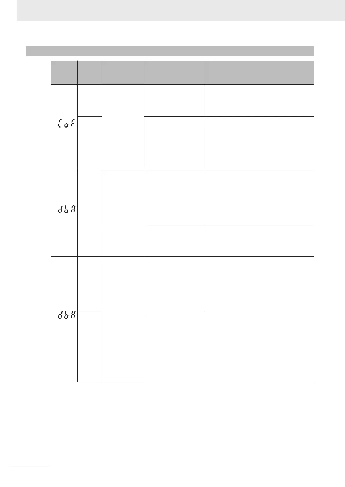
Alarm Code List
Alarm
code
Alarm
sub-
code
Name Description Check point and remedy reference
(Cof)
1
Current input
terminal
AI2(AII) signal
disconnection
(1) Current input com-
mand disconnection
Check that current input terminals AI2(AII)*
are receiving current.
→ Terminal AI2(AII) disconnection detec-
tion “Subcode: 1”
(2) Strong noise re-
ceived from surrounds
Check measures against noise (grounding
conditions, signal wiring and communication
cable/main circuit wiring and installation
methods, etc.)
→ Strengthen measures against noise.
→ Separate main circuit wiring and control
circuit wiring as much as possible.
(dbA)
Braking transis-
tor error
Error in braking resistor
connection terminal wir-
ing
Check that the braking resistor is correctly
wired in to the [P+] and [DB] terminals on the
main circuit terminal block.
Check that the motor wiring is not erroneous-
ly connected to the terminal [DB].
→ If there is no miswiring, request repair
of the inverter
.
The braking transistor
is damaged.
Check that the braking resistor value is cor-
rect, and that it is not miswired.
→
If there is no problem, request repair of
the inverter.
(dbH)
0
Braking resistor
overheat
(1) High braking load Re-calculate the relationship between brak-
ing load calculations and braking capacity.
→ Reduce braking load.
→ Review braking resistor selection, and
increase braking capacity.
(Resetting of parameters F50, F51, F52
data is necessary)
0
(2) Short deceleration
time
Recalculate deceleration torque and deceler-
ation time required from the moment of iner-
tia of the load and deceleration time.
→ Lengthen deceleration time (parame-
ters F08, E1
1, E13, E15, H56)
→
Review braking resistor selection, and
increase braking capacity.
(Resetting of parameters F50, F51, F52
data is necessary)
9 Troubleshooting
9-4
M1 Series Standard Type User's Manual (I669)
 Loading...