5-1SectionConnecting to the Host’s RS-422A/485 Port
92
5-1-5 1:N Connection to the Host’s RS-485 Port
This
section explains how to connect the RS-232C ports of two or more NT21s
with the host’s RS-485 port through Link Adapters.
NS-AL002
Link Adapters
are required to convert communications methods be
-
tween the RS-232C and RS-485 formats.
Reference: S The
RS-485
standard
1:N NT link method can be used only when the follow
-
ing Boards/Units are installed:
CS1W-SCB41 Serial Communications Board in a CS-series CS1G/H(-H)
CJ1W-SCU41 Serial Communications Unit in a CJ-series CJ1G
Serial Communications Board in a C200HX/HG/HE(-Z)E
CQM1H-SCB41 Serial Communications Board in a CQM1H
S The
RS-485
high-speed
1:N NT link method can be
used only when the follow
-
ing Boards/Units are installed:
CS1W-SCB41 Serial Communications Board in a CS-series CS1G/H(-H)
CJ1W-SCU41 Serial Communications Unit in a CJ-series CJ1G
Connecting the NT21s to the Link Adapters (RS-232C)
The
RS-232C connections between the NT21s
and Link Adapters in a 1:N con
-
figuration
is the same as the connection in a 1:1 RS-422A configuration. Refer to
Connecting
the NT21 to the Link Adapter (RS-232C)
on page
85 for details on
the RS-232C connections.
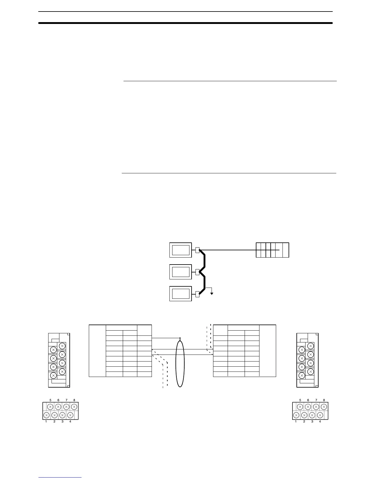
Connecting the Link Adapters between NT21s (RS-485)
RS-485
(Total length:
500 m max.)
NT21 Host
Link Adapter
(NT-AL001 or
NS-AL002)
Pin number Abbreviation
F. Ground
SG
SDB
SDA
RDB
RDA
CSB
CSA
DIP Switch Settings
NT-AL001: Pins 1, 3, 4, and 6 ON
Pins 2 and 5 OFF
(Turn ON pin 2 to enable the
terminator in the last Unit.)
NS-AL002: Pin 1 to 3 ON
Pin 4 OFF
(Turn ON pin 4 to enable the
terminator in the last Unit.)
Link Adapter
RS-422A
terminal
block
NT-AL001
1
2
3
4
5
6
7
8
NS-AL002
1
---
3
7
2
6
---
---
Pin numberAbbreviation
F. Ground
SG
SDB
SDA
RDB
RDA
CSB
CSA
DIP Switch Settings
NT-AL001: Pins 1, 3, 4, and 6 ON
Pins 2 and 5 OFF
(Turn ON pin 2 to enable the
terminator in the last Unit.)
NS-AL002: Pin 1 to 3 ON
Pin 4 OFF
(Turn ON pin 4 to enable the
terminator in the last Unit.)
Link Adapter
RS-422A
connector
NT-AL001
1
2
3
4
5
6
7
8
NS-AL002
1
---
3
7
2
6
---
---
Shield
NS-AL002
NT-AL001
7
5
3
1
8
6
4
2
NS-AL002
NT-AL001
7
5
3
1
8
6
4
2
To avoid an FG ground loop, connect the functional ground of only one of the
Link Adapters to the shielding of the RS-485 cable.

 Loading...


