3-5SectionUsing a Memory Unit
32
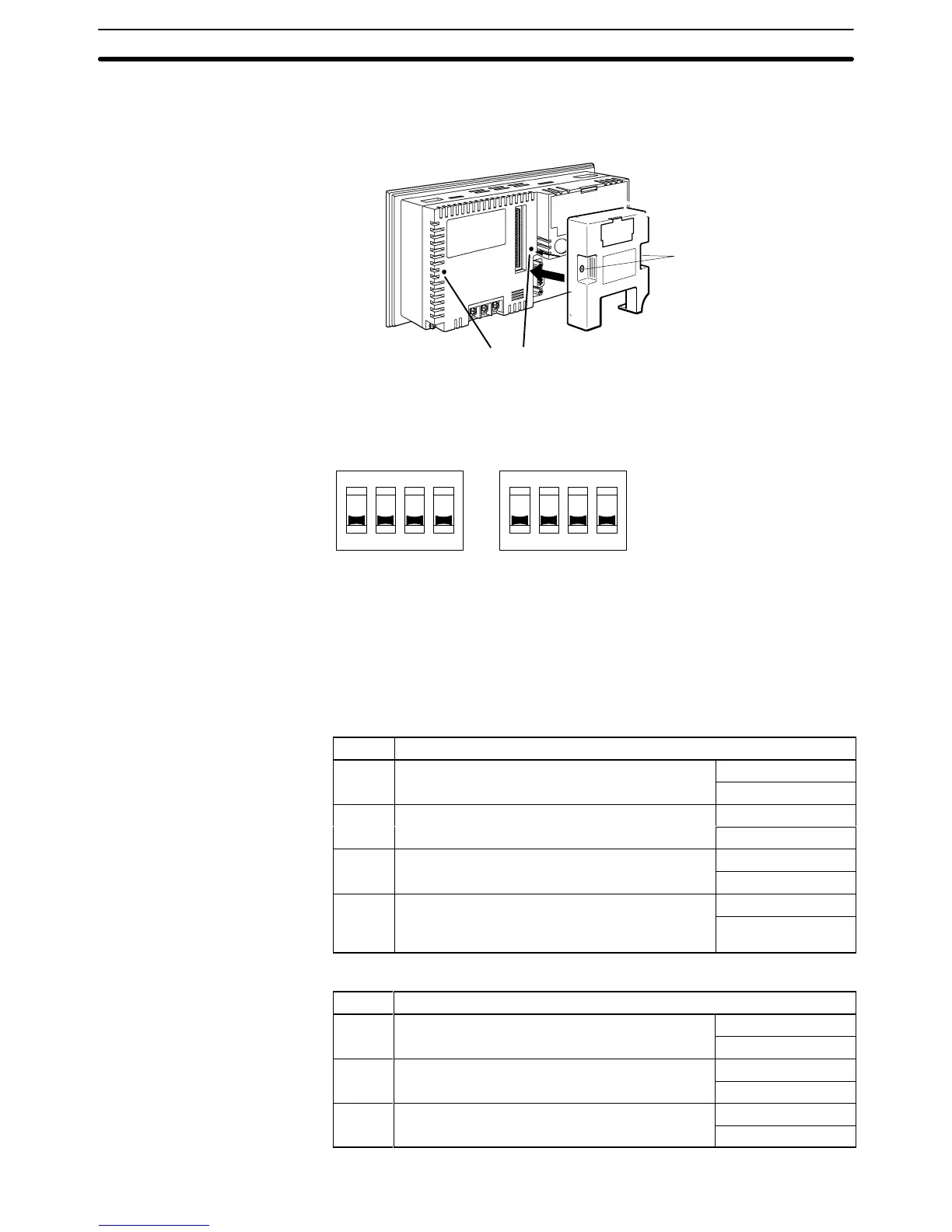
3-5-1 Installation Method
Install
the Memory Unit (NT
-MF261) at the
expansion interface connector at the
rear of the NT21 as shown in the figure below.
Mounting screws
Screw hole
3-5-2 Method of Use
As
shown in the figure below
, a Memory Unit has 2 four-pin DIP switches, and
the operation is determined by the DIP switch settings at startup.
4321
OFF
SW1 SW2
OFF
4321
Factory
setting is turned all to OFF
.
Note Always confirm that the power to the NT21 is OFF before setting the DIP
switches.
The
functions of the DIP switches on the Memory Unit are indicated in the table
below.
• SW1
Pin Function

 Loading...


