3-3SectionConnecting the NT Support Tool
28
grounding
points. W
e recommend grounding the shield at one end, as shown in
the following diagram.
RS-232C
RS-232C
RS-232C
Connect
to the
terminal block’
s
FG terminal.
NT21
NT21
NT21
Host
RS-422A/485
shield
Signal lines
NT-AL001
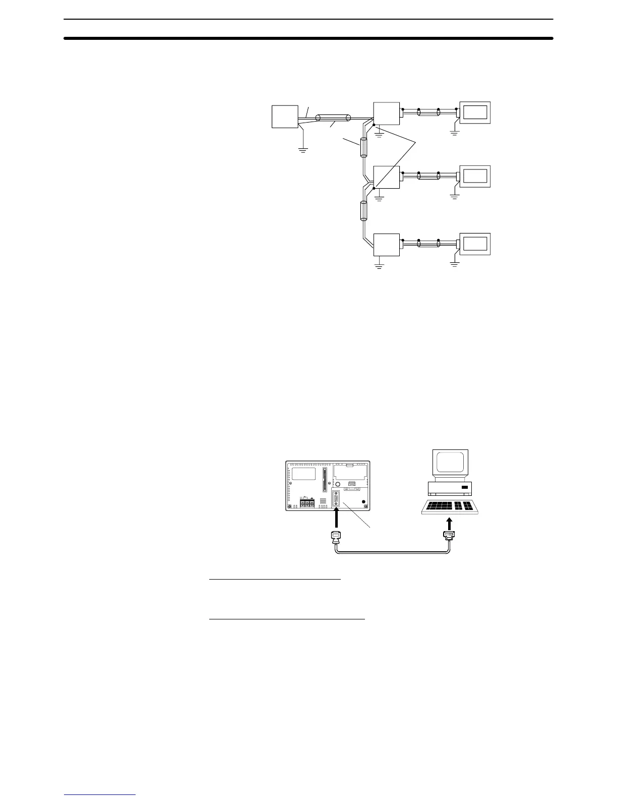
3-3 Connecting the NT Support Tool
In order to install the system program in the NT21, or to transmit screen data
created
with the NT Support T
ool to the NT21, the NT21 must be connected to a
personal computer with an RS-232C cable.
The
NT21 connects with
the RS-232C cable from a personal computer at serial
port
A. When the host is connected at serial port B, the connection with the host
can be maintained as it is while the NT21 is connected to the RS-232C cable
from a personal computer.
However,
when a bar
code reader is being used, it must be disconnected, so that
the RS-232C cable can be connected, since they both use serial port A.
Serial
port A
(RS-232C, 9-pin)
Communication Conditions
The
communication conditions are automatically set when the system installer
and NT Support Tool are started.
Recommended Connector Cable
Use the cable indicated below.
• CV500-CN228 (length: 2 m), made by OMRON
(D-SUB 9-pin, male ⇔ D-SUB 25-pin, male)
• XW2Z-S001 (conversion cable), made by OMRON
(D-SUB 25-pin, female ⇔ half pitch 14-pin, male)
• XW2Z-S002 (length: 2 m), made by OMRON
(D-SUB 9-pin, male ⇔ D-SUB 9-pin, female)
For
details on making a connector cable, refer to
Appendix E Making the Cable
for Connecting a PC (page 199).

 Loading...


